
Andrew Huang's Blog, page 24
June 5, 2018
Developing Apps for Your TV the Easy and Open Way
The biggest screen in your house would seem a logical place to integrate cloud apps, but TVs are walled gardens. While it’s easy enough to hook up a laptop or PC and pop open a browser, there’s no simple, open framework for integrating all that wonderful data over
the TV’s other inputs.
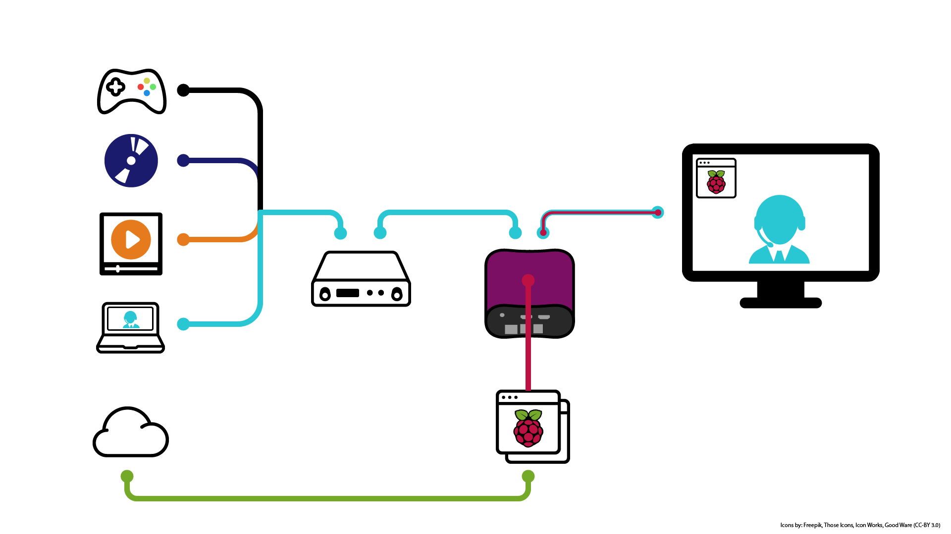
Until now. Out of the box, NeTV2’s “NeTV Classic Mode” makes short work of overlaying graphics on top of any video feed. And thanks to the Raspberry Pi bundled in the Quickstart version, NeTV2 app developers get to choose from a diverse and well-supported ecosystem of app frameworks to install over the base Raspbian image shipped with every device.
For example, Alasdair Allan’s article on using the Raspberry Pi with Magic Mirror and Google AIY contains everything you need to get started on turning your TV into a voice-activated personal assistant. I gave it a whirl, and in just one evening I was able to concoct the demo featured in the video below.
Magic Mirror is a great match for NeTV2, because all the widgets are formatted to run on a black background. Once loaded, I just had to set the NeTV2’s chroma key color to black and the compositing works perfectly. Also, Google AIY’s Voicekit framework “just worked” out of the box. The only fussy bit was configuring it to work with my USB microphone, but thankfully there’s a nice Hackaday article detailing exactly how to do that.
Personally, I find listening to long-form replies from digital assistants like Alexa or Google Home a bit time consuming. As you can see from this demo, NeTV2 lets you build a digital assistant that pops up data and notifications over the biggest screen in your house using rich visual formats. And the best part is, when you want privacy, you can just unplug the microphone.
If you can develop an app that runs on a Raspberry Pi, you already know everything you need to integrate apps into any TV. Thanks to NeTV2, there’s never been an easier or more open way to make the biggest screen in your house the smartest screen.
The NeTV2 is crowdfunding now at CrowdSupply.com, and we’re just shy of our first stretch goal: a free Tomu bundled with every board. Normally priced at $30, Tomu is a tiny open-source computer that fits in a USB Type-A port, and it’s the easiest way to add an extra pair of status LEDs to an NeTV2. Help unlock this deal by backing now and spreading the word!


June 3, 2018
Name that Ware, June 2018
The Ware for June 2018 is shown below.
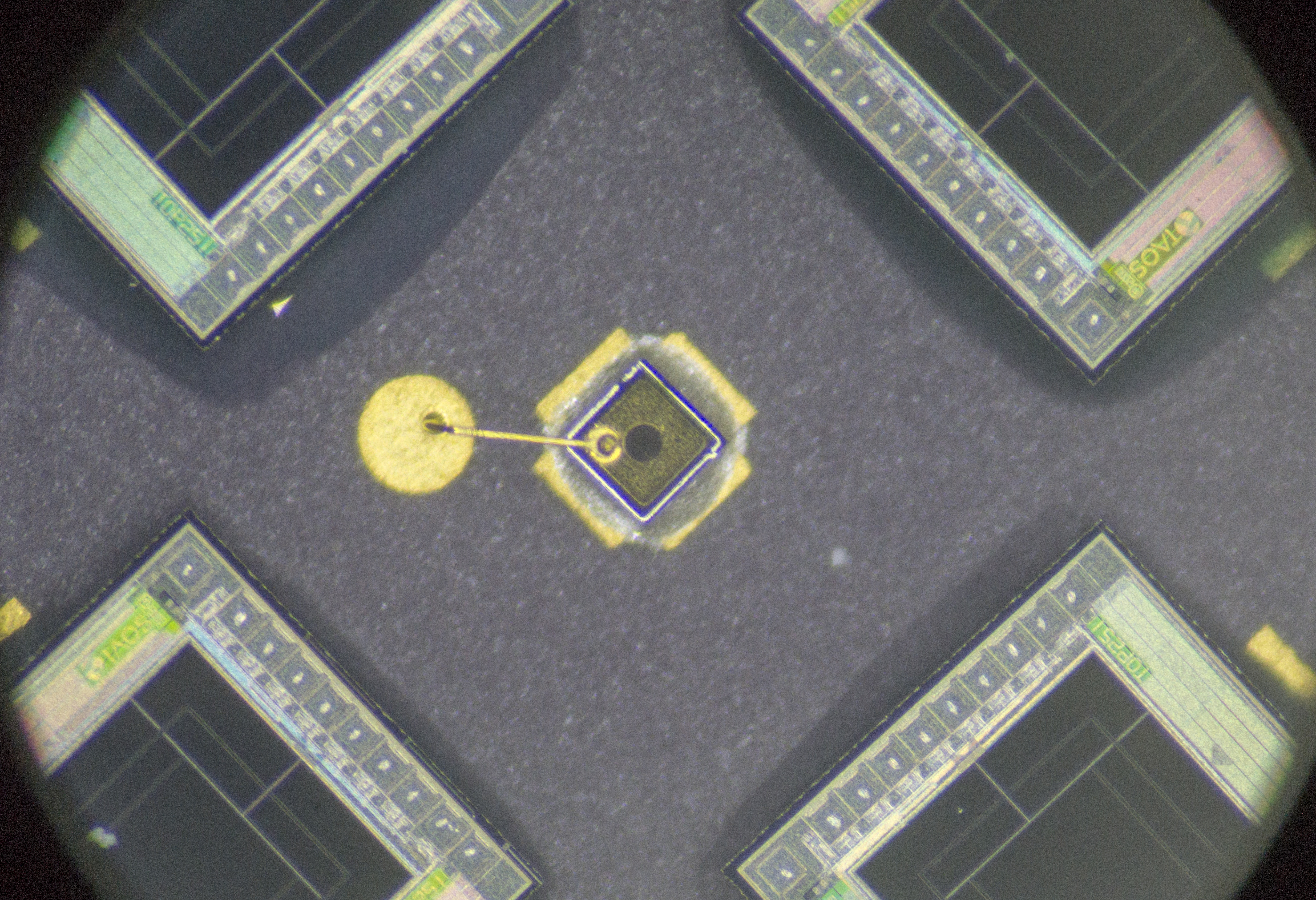
This month we’ll start with the very zoomed in and slightly torn down view of the ware, and if nobody’s nailed it I’ll release some more contextual images throughout the month.
Special thanks to Nava for giving me this ware!
Winner, Name that Ware May 2018
The NeTV2-MVP DVT1E rev shown in the May 2018 ware has 933 vias and 63 holes for a total of 996 drill hits. The closest guess for total number of drill hits was Jonathan, at 69 holes and 888 vias = 957 drill hits (39 shy of the total). Mangel was in a close second place with 84 hols and 962 vias for a total of 1046 drill hits (50 over the total). So, Jonathan’s the winner! Congrats, please email me to claim your board!
May 11, 2018
Innovation Should Be Legal. That’s Why I’m Launching NeTV2.
I’d like to share a project I’m working on that could have an impact on your future freedoms in the digital age. It’s an open video development board I call NeTV2.
The Motivation
It’s related to a lawsuit I’ve filed with the help of the EFF against the US government to reform Section 1201 of the DMCA. Currently, Section 1201 imbues media cartels with nearly unchecked power to prevent us from innovating and expressing ourselves, thus restricting our right to free speech.
Have you ever noticed how smart TVs seem pretty dumb compared to our phones? It’s because Section 1201 enables a small cartel of stakeholders to pick and choose who gets to process video. So, for example, anyone is allowed to write a translation app for their smartphone that does real-time video translation of text. However, it’s potentially unlawful to build a box, even in the privacy of my own home, that implements the same thing over the HDCP-encrypted video feeds that go from my set top box to my TV screen.
This is due to a quirk of the DMCA that makes it unlawful for most citizens to bypass encryption – even for lawful free-speech activities, such as self-expression and innovation. Significantly, since the founding of the United States, it’s been unlawful to make copies of copyrighted work, and I believe the already stiff penalties for violating copyright law offer sufficient protection from piracy and theft.
However, in 1998 a group of lobbyists managed to convince Congress that the digital millennium presented an existential threat to copyright holders, and thus stiffer penalties were needed for the mere act of bypassing encryption, no matter the reason. These penalties are in addition to the existing penalties written into copyright law. By passing this law, Congress effectively turned bypassing encryption into a form of pre-crime, empowering copyright holders to be the sole judge, jury and executioner of what your intentions might have been. Thus, even if you were to bypass encryption solely for lawful purposes, such as processing video to translate text, the copyright holder nonetheless has the power to prosecute you for the “pre-crimes” that could follow from bypassing their encryption scheme. In this way, Section 1201 of the DMCA effectively gives corporations the power to license when and how you express yourself where encryption is involved.
I believe unchecked power to license freedom of expression should not be trusted to corporate interests. Encryption is important for privacy and security, and is winding its way into every corner of our life. It’s fundamentally a good thing, but we need to make sure that corporations can’t abuse Section 1201 to also control every corner of our life. In our digital age, the very canvas upon which we paint our thoughts can be access-controlled with cryptography, and we need the absolute right to paint our thoughts freely and share them broadly if we are to continue to live in a free and just society. Significantly, this does not diminish the power of copyrights one bit – this lawsuit simply aims to limit the expansive “pre-crime” powers granted to license holders, that is all.
Of course, even though the lawsuit is in progress, corporations still have the right to go after developers like you and me for the notional pre-crimes associated with bypassing encryption. However, one significant objection lodged by opponents of our lawsuit is that “no other users have specified how they are adversely affected by HDCP in their ability to make specific noninfringing use of protected content … [bunnie] has failed to demonstrate … how “users ‘are, or are likely to be,’ adversely affected by the prohibition on circumventing HDCP.” This is, of course, a Catch-22, because how can you build a user base to demonstrate the need for freedoms when the mere act of trying to build that user base could be a crime in itself? No investor would touch a product that could be potentially unlawful.
Thankfully, it’s 2018 and we have crowd funding, so I’m launching a crowd funding campaign for the NeTV2, in the hopes of rallying like-minded developers, dreamers, users, and enthusiasts to help build the case that a small but important group of people can and would do more, if only we had the right to do so. As limited by the prevailing law, the NeTV2 can only process unencrypted video and perform encryption-only operations like video overlays through a trick I call “NeTV mode”. However, it’s my hope this is a sufficient platform to stir the imagination of developers and users, so that together we can paint a vibrant picture of what a future looks like should we have the right to express our ideas using otherwise controlled paints on otherwise denied canvases.

Some of the things you might be able to do with the NeTV2, if you only had the right to do it…
The Hardware
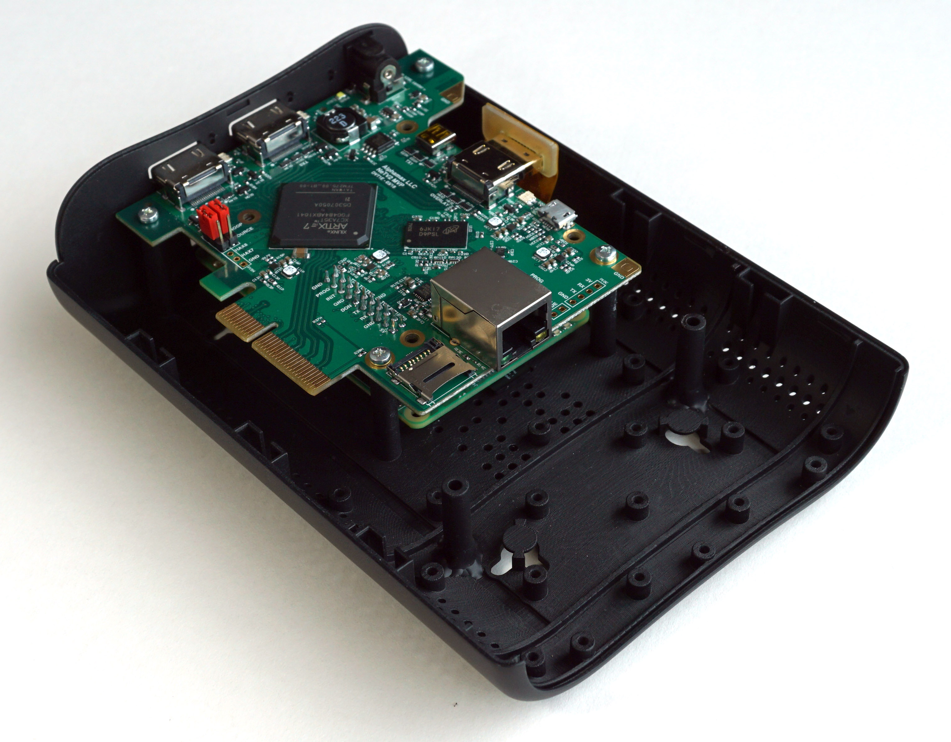
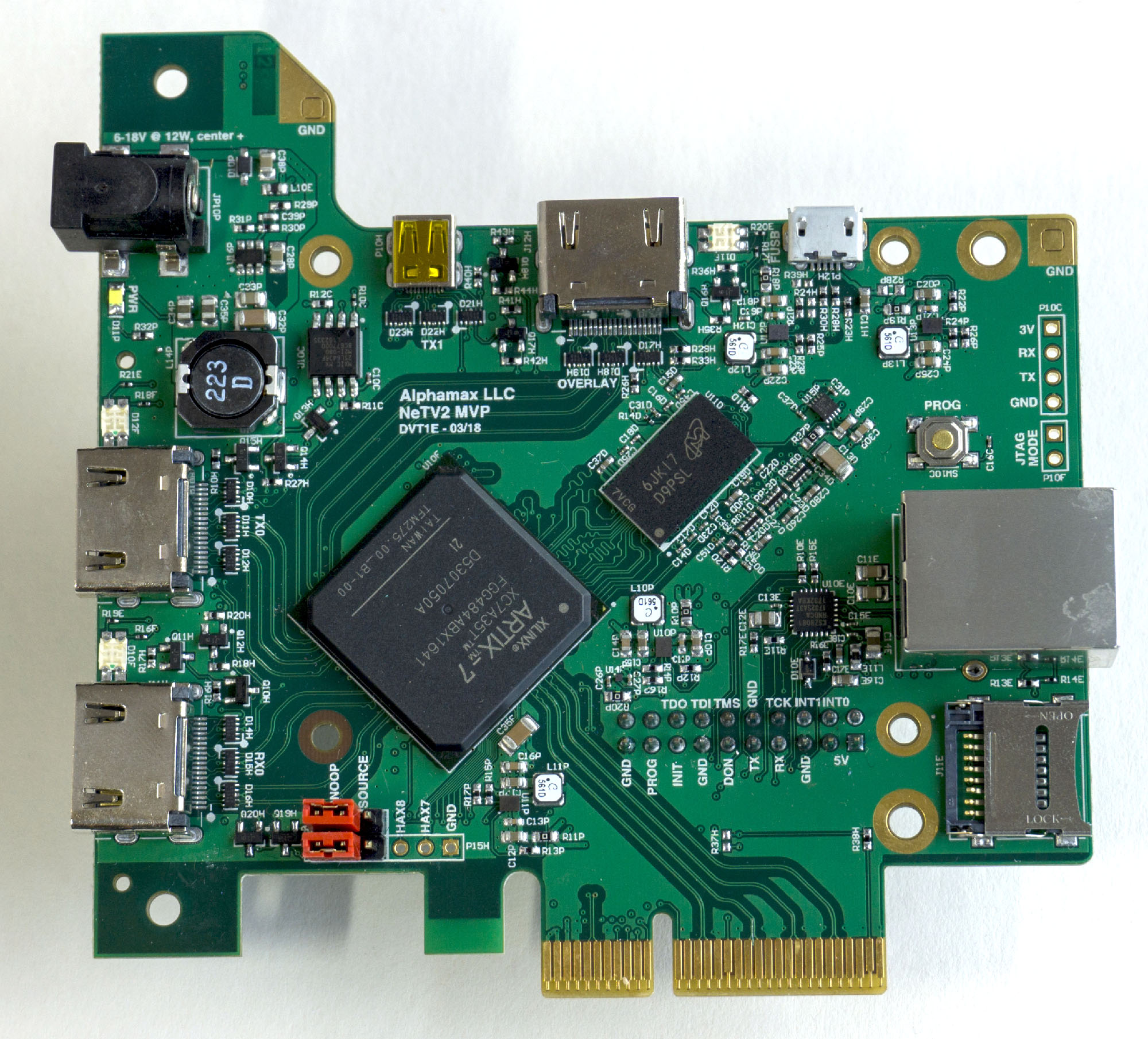
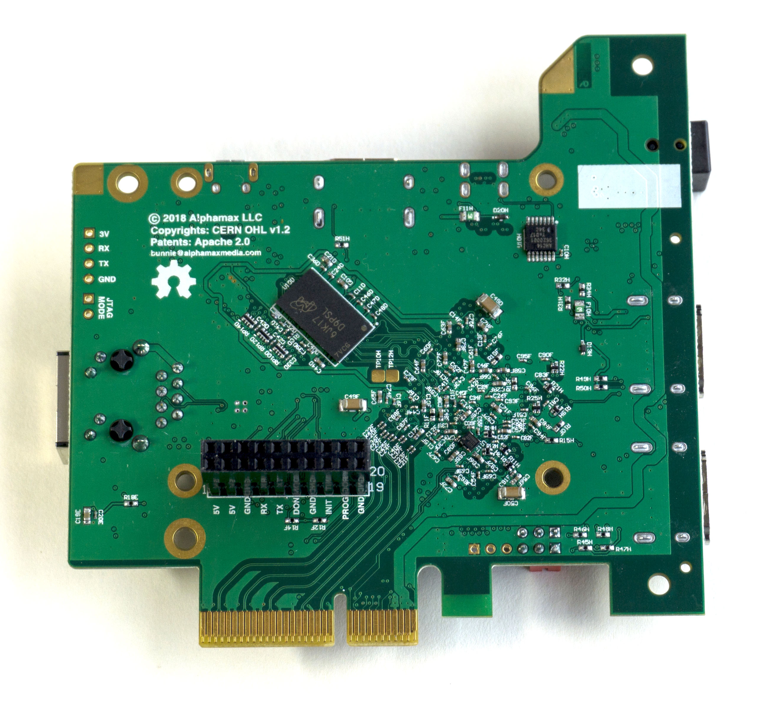
The heart of the NeTV2 is an FPGA-based video development board in a PCIe 2.0 x4 card form factor. The board supports up to two video inputs and two video outputs at 1080p60, coupled to a Xilinx XC7A35T FPGA, along with 512 MiB of DDR3 memory humming along at a peak bandwidth of 25.6 Gbps. It also features some nice touches for debugging including a JTAG/UART header made to plug directly into a Raspberry Pi, and a 10/100 Ethernet port wired directly to the FPGA for Etherbone support. For intrepid hackers, the reserved/JTAG pins on the PCI-express header are all wired to the FPGA, and microSD and USB headers are provisioned but not specifically supported in any mode. And of course, the entire PCB design is open source under the CERN OHL license.
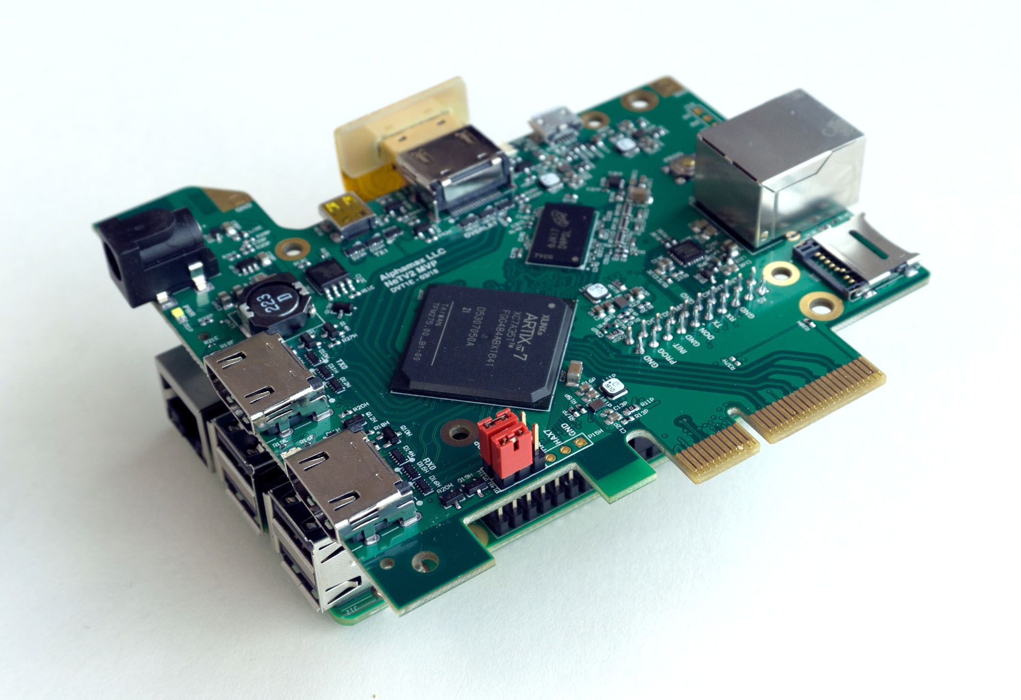
The NeTV2 board as mounted on a Raspberry Pi
The design targets two major use scenarios which I refer to as “NeTV classic” mode (video overlays with encryption) and “Libre” mode (deep video processing, but limited to unencrypted feeds due to Section 1201).
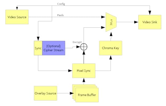
In NeTV classic mode, the board is paired with a Raspberry Pi, which serves as the source for chroma key overlay video, typically rendered by a browser running in full-screen mode. The Raspberry Pi’s unencrypted HDMI video output is fed into the NeTV2 and sampled into a frame buffer, which is “genlocked” (e.g. timing synchronized) to a video feed that’s just passing through the FPGA via another pair of HDMI input/outputs. The NeTV2 has special circuits to help observe and synchronize with cryptographic state, should one exist on the pass-through video link. This allows the NeTV2 to encrypt the Raspberry Pi’s overlay feed so that the Pi’s pixels can be used for a simple “hard overlay” effect. NeTV classic mode thus enables applications such as subtitles and pop-up notifications by throwing away regions of source video and replacing it entirely with overlay pixels. However, a lack of access to unencrypted pixels disallows even basic video effects such as alpha blending or frame scaling.
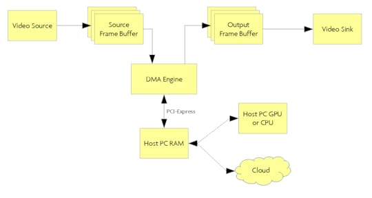
In Libre mode, the board is meant to be plugged into a desktop PC via PCI-express. Libre mode only works with unencrypted video feeds, as the concept here is full video frames are sampled and buffered up inside NeTV2 so that it can be forwarded on to the host PC for further processing. Here, the full power of a GPU or x86 CPU can be applied to extract features and enhance the video, or perhaps portions of the video could even be sent to to the cloud for processing. Once the video has been processed, it is pushed back into the NeTV2 and sent on to the TV for viewing. Libre mode is perhaps the most interesting mode to developers, yet is very limited in every day applications thanks to Section 1201 of the DMCA. Still, it may be possible to craft demos using properly licensed, unencrypted video feeds.
The reference “gateware” (FPGA design) for the NeTV2 is written in Python using migen/LiteX. I previously compared the performance of LiteX to Vivado: for an NeTV2-like reference design, the migen/LiteX version consumes about a quarter the area and compiles in less than a quarter the time – a compelling advantage. migen/LiteX is a true open source framework for describing hardware, which relies on Xilinx’s free-to-download Vivado toolchain for synthesis, place/route, and bitstream generation. There is a significant effort on-going today to port the full open source FPGA backend tools developed by Clifford Wolf from the Lattice ICE40 FPGAs to the same Xilinx 7-series FPGAs used in NeTV2. Of course, designers that prefer to use the Vivado tools to describe and compile their hardware are still free to do so, but I am not officially supporting that design methodology.
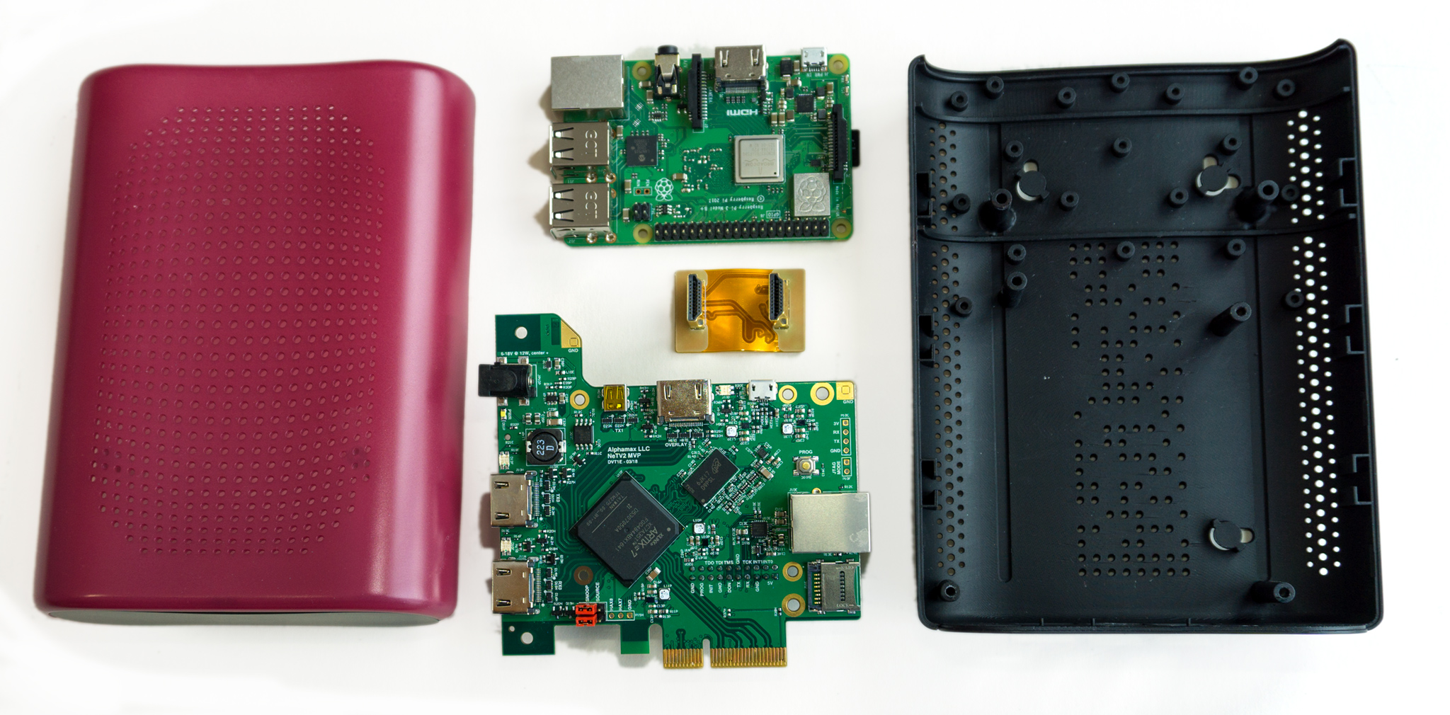
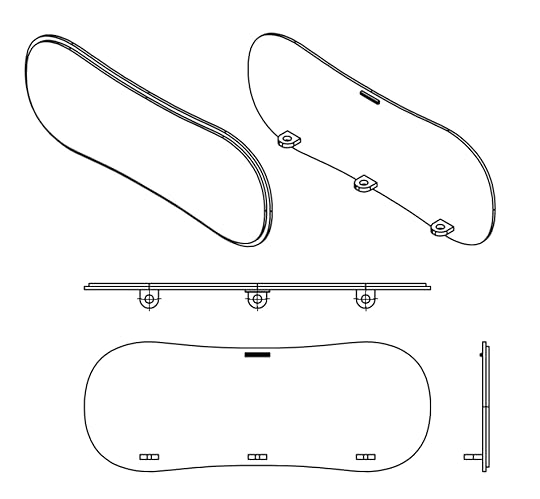
I wanted to narrow the gap between development board and field deployable solution, so I’ve also designed a hackable case for the NeTV2. The case can hold the NeTV2 and a mated Raspberry Pi, and consists of three major parts, a top shell, bottom shell/back bezel, and a stand-alone front bezel. It also has light pipes to route key status LEDs to the plane of the back bezel. It’s designed to be easily disassembled using common screw drivers, and features holes for easy wall-mounting.
Most importantly, the case features extra space with a Peek Array on the inside for mounting your own PCBs or parts, and the front bezel is designed for easier fabrication using either subtractive or additive methodologies. So, if you have a laser cutter, you can custom cut a bezel using a simple, thin sheet of acrylic and slot it into the grooves circumscribing the end of the case. Or, if you have a low-res 3D printer, you can use the screw bosses to attach the bezel instead, and skip the grooves. When you’re ready to step up in volume, you can download the source file for the bezel and make a relatively simple injection mold tool for just the bezel itself (or the whole case, if you really want to!).
The flexibility of the PCI-express edge connector and the simplified bezel allows developers to extend the NeTV2 into a system well beyond the original design intention. Remember, for an FPGA, PCI-express is just a low-cost physical form factor for generic high speed I/O. So, a relatively simple to design and cheap to fabricate adapter card can turn the PCI-express card-edge connector into a variety of high-speed physical standards, including SATA, DisplayPort, USB3.0 and more. There’s also extra low-speed I/O in the header, so you can attach a variety of SPI or I2C peripherals through the same connector. This electrical flexibility, combined with PCBs mounted on the Peek Array and a custom bezel enables developers to build a customer-ready solutions with minimal effort and tooling investment.
The NeTV2 is funding now at Crowd Supply. I’m offering a version with a higher-capacity FPGA only for the duration of the campaign, so if you’re developer be sure to check that out before the campaign ends. If you think that reforming the DMCA is important but the NeTV2 isn’t your cup of tea, please consider supporting the EFF directly with a donation. Together we can reform Section 1201 of the DMCA, and win back fundamental freedoms to express and innovate in the digital age.
Name that Ware, May 2018
The Ware for May 2018 is shown below.
This month’s contest isn’t about naming a ware. Instead, the challenge is to guess the total amount of vias + holes on the NeTV2 PCB. The closest (or first correct) guess will get a DVT-revision of the board (same as the one shown above) as a prize! Please note: depending on your country of residence you may have to cover import duties or VAT.
At the end of this month, once the contest is over, I’ll upload the PCB source files to a public repo. The contest would be just too easy otherwise :)
Winner, Name that Ware April 2018
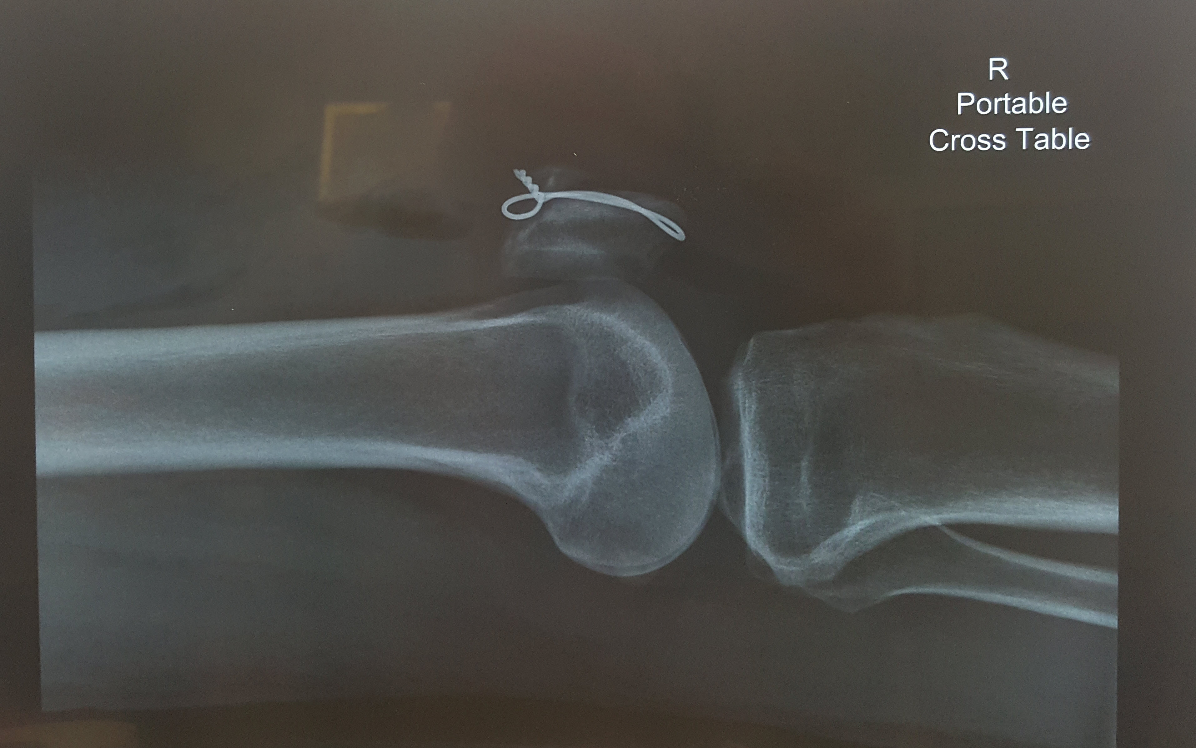
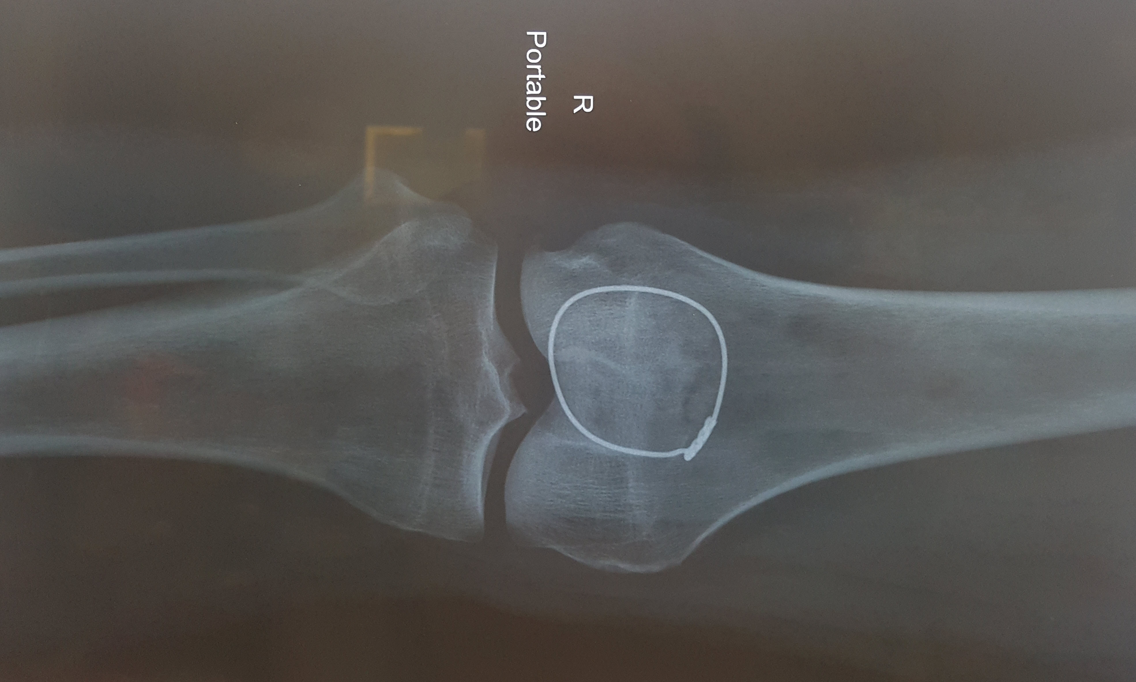
The ware for April 2018 is an SAE 316L stainless steel cerclage currently embedded in my right kneecap. There’s also a pair of 2.5mm holes drilled lengthwise through the patella, and a set of sutures woven into my quadriceps, neither of which show up in an X-ray. The hardware is to repair a double-break of my knee; I simultaneously suffered a patellar avulsion fracture and a tear of the quadriceps tendon. It’s rare to get both injuries at once, but hey why do anything half-assed. As for how it happened – well, you’ll have to believe me that it’s just from falling while walking on flat ground. There was a puddle of greasy/soapy water outside a hawker stall and boom, I’m unable to walk for months. I wish I had some cooler story, so that’s why I had this month’s competition – to try and find a better bar story. To that end, gratz to perlfriend for the most imaginative story; email me for your prize!
This was my first time going through major surgery. I’ve previously had some minor patches and cuts, where I only used local anesthesia and watched the surgeon perform. As a hardware guy, I think your body is the most fascinating piece of hardware you’ll ever own so I don’t miss an opportunity to take a peek inside when maintenance is required (to clarify, I find it totally gross to watch other people’s surgeries, but somehow when it’s my own body its different – my sense of wonder overtakes my aversion to blood).
So I’ve never been put full under before. When the anesthesiologist came to interview me, I asked what my options were for local anesthesia. She then tried to convince me that general anesthesia is very safe because they have this computer running some complicated algorithm that considers my weight and height to dose me correctly. Besides the fact that they had to estimate my weight because I couldn’t stand on a scale, my inner monologue was screaming “As a hardware engineer, putting my life in the hands of a computer sounds terrifying” but instead I manage to ask politely, “and what happens if the computer has a problem?” At which point she smiles and re-assures me that she’s constantly monitoring my vital signs and trimming the dosage.
Side note, a friend of mine later on pointed me to an article where apparently some infusion pumps have Wifi that’s on during surgery and the protocol is pathetically hackable. OK, medical equipment makers: there’s some equipment that simply should not be IoT, and an infusion pump is absolutely one of them. There is simply no valid reason for the computer attending to the dosage level of a potentially fatal chemical to be spending any cycles answering TCP packets. Death by DDoS is not an acceptable scenario. If you need to push an update, do it by a USB disk or a plug-in Ethernet jack, so they can at least air gap the damn thing during an operation.
Had I known about the wifi vulnerability of anesthesia infusion pumps, I probably would not have consented to general anesthesia, or at least asked to check that the model they were using had no IoT capability. But the anesthesiologist finally convinced me under the argument that the local procedure would require sticking a needle into my spinal cord and withdrawing cerebrospinal fluid, and I’m like, I don’t know what that is but it sounds important for my brain to work and I kind of like my spinal cord intact, so maybe it’s not worth the risk.
So, I finally consent to being put under. Propofol, the drug she used to initiate anesthesia, is pretty incredible. It acts within seconds, and despite taking over an hour to metabolise in the liver, it clears from the brain in minutes so you can come out of anesthesia quickly. I have to wonder how they discovered it, or developed it. Anyways, the anesthesiologist inserted an IV into my right hand – I appreciated her attentiveness to the detail that I’m left-handed – and proceeded to administer the propofol. I could definitely feel the propofol as it entered my system. I had the same feeling of pins and needles that one gets when a limb falls asleep, a sort of searing, prickling pain. The pain quickly shot up my arm, then a warm wave of prickling across my face, and then…
I’m in the recovery room, and my surgeon is there giving me the post-op interview. About 2.5 hours of my life went by and I had no memory of it. Sure enough, no nausea or dizziness – the anesthesiologist did a good job. I was lucid and talking to the surgeon about the operation. Then, maybe about five or maybe fifteen minutes later, my body goes into shock – I’m shivering uncontrollably, and I’m starting to become acutely aware of the pain in my knee.
Apparently, during the surgery, I was given Fentanyl and Ultiva, both potent opioid painkillers. They give it to you because even though you’re out, your body has autonomous responses to pain that can complicate surgery with excess bleeding and so forth. From what I read, both clear pretty quickly, so I’m guessing the onset of shock corresponded with the painkilling effect of the injected opioids wearing off.
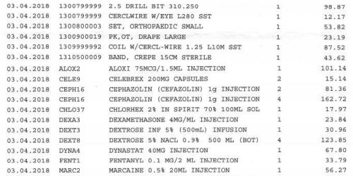
I know exactly what drugs and equipment they used because at the conclusion of the surgery I was given a detailed itemized bill of everything involved; above is a tiny sample of it. It was fascinating to reverse engineer the surgery from the BOM. That’s how I knew they used a 2.5mm drill bit, how I knew they put a breathing tube in me, and that I also got injected with Aloxi to help suppress nausea. I actually sort of wish I knew about the drill bit ahead of time, because I would have asked to keep it. I figured they’re throwing it away so getting the surgical-grade 2.5mm bit that was used to drill holes in my body to use later on to drill mounting bosses would be pretty neat.
Just for the record, the overall hospital bill including surgeon’s fees, surgical materials, OT rental, recovery ward, drugs, X-rays and my first round of physiotherapy was about S$20.7k, or US$15.5k at the prevailing exchange rate. This is considered expensive by Singapore standards, as I went to one of the nicer private hospitals for the operation, but as I understand it is quite cheap by US standards. Fortunately my insurance covered all but about $350 of it.
This was also my first time using opioid painkillers in a serious way. I’m deeply concerned about the addictive nature of opioids, so I don’t take them lightly. I had taken Vicodin once before when I had a wisdom tooth removed, and I remember it having the effect of “moving the pain sideways” – it felt like the pain was just outside arms length, so I could ignore it if I wanted to, but I definitely knew it was still there. Knee surgery was about a hundred times more traumatic than getting a wisdom tooth removed, and for the first day there’s a terrific amount of pain. So they gave me Targin, which is a mix of oxycodone and naloxone.
Targin is a clever way to manage opioid addictiveness. Oxycodone is the opioid; naloxone is the stuff they use to treat opioid overdoses, and it blocks the painkilling effects. Nalaxone is mixed in with the oxycodone to prevent mis-use (crushing & snorting or injecting), and naloxone is poorly absorbed through the digestive system, so when taken orally the oxycodone can still work. For a short time. When the surgical painkillers wore out, basically all the pain receptors in my knee were screaming at me and informing me rather viscerally about what I already knew intellectually – that my knee was cut up, had holes drilled in it, wired up with stainless steel, fibers woven into the muscles, and stitched back together. So I got one dose of Targin, which kicked in in about 20-30 minutes. The oxycodone effect was pretty strong – the acute pain just went away, everything felt okay and I drifted into sleep…only to be woken up about 2-3 hours later by the pain in my knee, presumably due to the nalaxone component finally kicking in and suppressing the opioid effect. However, I was only allowed one Targin pill every 12 hours, and thus had only acetaminophen to manage the pain until the next scheduled dose. It was definitely manageable with some distraction, but there was no way I was going back to sleep again. I could see how oxycodone could be addictive; everything just seemed so okay despite everything being incredibly wrong, so I’m grateful they mixed it with nalaxone and administered it such that my final memory of the trip was being clobbered with my knee pain rather than a lingering desire for more.
Of course, the pain doen’t end in 24 hours, but they “graduated” me to a weaker painkiller, Ultracet. The Ultracet is a mix of Tramadol and acetaminophen. Tramadol itself really kicks in only after it’s processed by the liver into desmetramadol by the enzyme CYP2D6, and I’m heterozygous for a copy with reduced activity. I guess that might explain why when I took the prescribed dosage of two pills it was reasonably effective, but when I halved it to one pill I felt almost nothing at all. Overall, Tramadol was less effective at painkilling and more effective in just making me feel a little dizzy and sleepy. In addition to binding to opioid receptors, it’s also a seratonin releasing agent, a bit like MDMA. So during the daytime I would just deal with the pain by distracting myself with work, and at night time when trying to fall asleep, I’d take the Ultracet and sleep like a baby – I was sleeping almost 12 hours a night for the couple weeks after surgery, which I think was extremely helpful in my recovery. Significantly, Tramadol doesn’t quite suppress pain; like my one experience with Vicoden, it turns it into a fact I’m aware of but can deal with. When I would sleep, my dreams would be deep and lucid, but my brain would often reference the pain in my knee and ascribe it to some random weird dream explanation, like trying to go in for a big penalty kick in a soccer game over and over again. Fortunately, Tramadol didn’t feel like it had too much of an addiction risk for me – the awake-state “high” was a bit unpleasant, as I don’t particularly enjoy the dizziness or drowsiness. It was more of a sleeping aid, as it allowed my mind to let go of the pain in my knee while falling asleep. I was finally able to wean myself off painkillers entirely and fall asleep drug-free about two weeks after the operation, but in a weird way I ever so slightly missed that really sound sleep I’d have while on them. Opioid painkillers are no joke. They’re absolutely essential for dealing with pain, but take them with discipline and caution.
While the story behind the accident itself wasn’t very interesting, I did find going through the surgery, healthcare system, and drugs to be an interesting learning experience.
April 24, 2018
Paper As a Substrate for Circuits
I’ve spent a considerable portion of my time in the past couple of years helping to develop products for Chibitronics, a startup that blends two unlikely bedfellows together, papercraft and electronics, to create paper circuits. The primary emphasis of Chibitronics is creating a more friendly way to learn, design and create electronics. Because of this, much of the material relating to paper circuitry on the Internet looks more like art than electronics.
This belies the capabilities of paper as an engineering material. Google’s Cardboard and Nintendo’s Labo are mainstream examples of paper’s extraordinary capability as an engineering material. Prof. Nadya Peek at the University of Washington has written several academic papers on building multi-axis CNC machines using paper products.
A couple points to clarify up top: for the sake of brevity, I will use the term “paper” instead of “paper and/or cardboard”, analogous to how one would refer to a PCB made of Kapton or FR-4 both as printed circuits. Furthermore, while Chibitronics focuses on providing solderless solutions for younger learners, the techniques shared in this post targets engineers who have the skill to routinely assemble modern SMT designs. I assume you’ve got a good soldering iron and a microscope, and you know how to use both (or perhaps are up to the challenge of learning how to use them better).
The Argument for Paper
For prototyping and learning the principles of electronics, paper has several distinct advantages over breadboards.
The primary advantage of a breadboard is that it’s solderless, and as a result you can re-use the components. This made a lot more sense back when a 6502 used to cost $25 in 1975 ($115 in 2018 money), but today the wire jumper kit for a solderless breadboard can cost more than the microcontroller. Considering also the relatively high cost of a solderless breadboard and the relatively low value of the parts, you’re probably better off buying extra parts and soldering them to disposable paper substrates than purchasing a re-usable solderless breadboard for all but the simplest of circuits.

Electronic components used to be really expensive, so you wanted to re-use them as much as possible. The 8-bit 6502 at $115 (adjusted for inflation) was considerably cheaper than its competition in 1975 (from Wikipedia).
On the other hand, paper has a number of important advantages. The first is that it’s compatible with surface mount ICs. This is increasingly important as chip vendors have largely abandoned DIP packages in favor of SMT packages: mobile computing represents the highest demand for chips, and SMT packages beat DIP packages in both thermal and parasitic electrical characteristics. So if you want a part that wasn’t designed by someone wearing a jean jacket and highwaters, you’re probably going to find it only available in SMT.
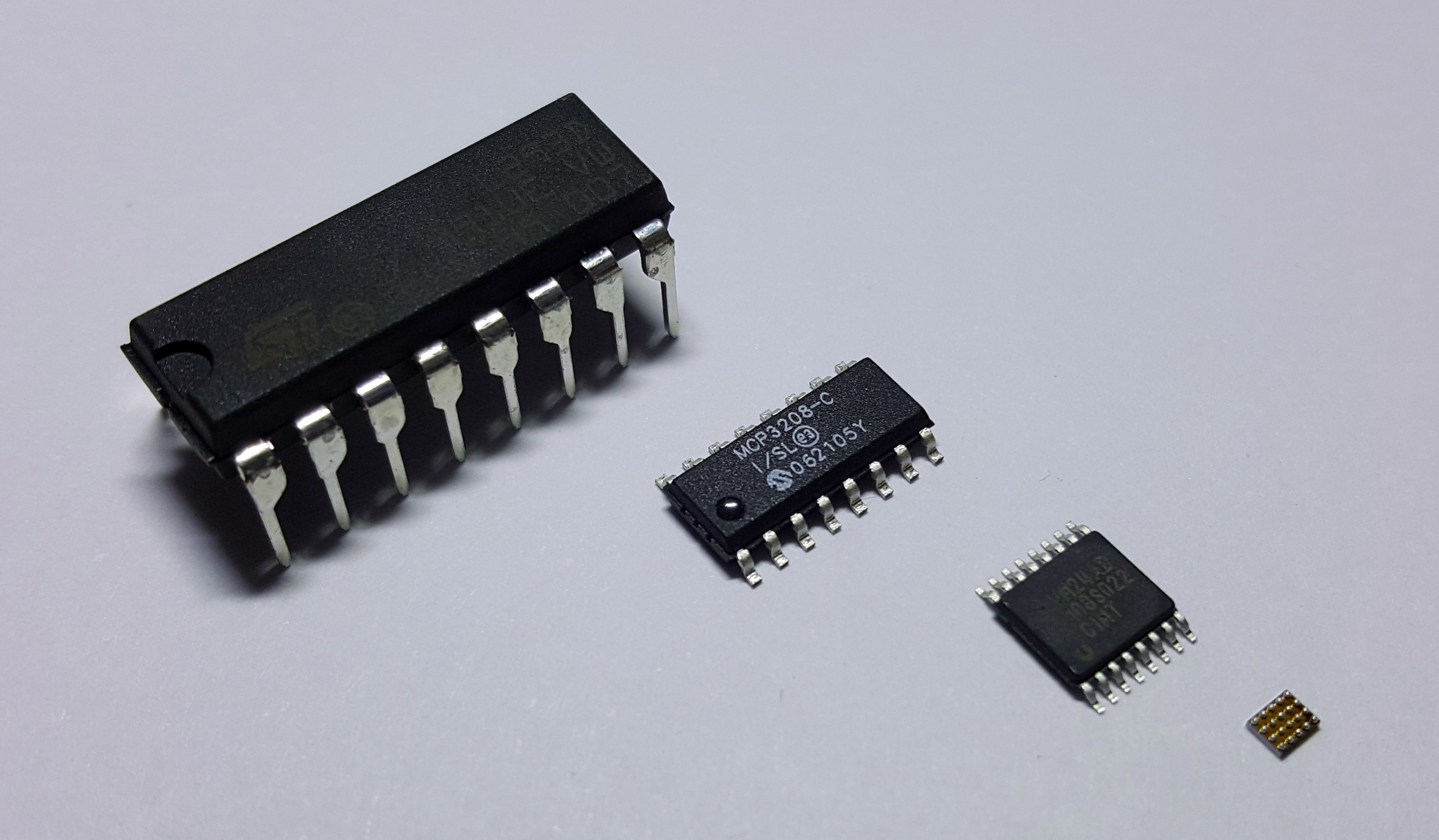
The evolution of packaging (from left to right): DIP, SOIC, TSSOP, and WLCSP. The WLCSP is shown upside-down so you can see how solder balls are applied directly to a naked silicon chip. It’s the asymptotic size limit of packaging, and is quite popular in mobile phones today.
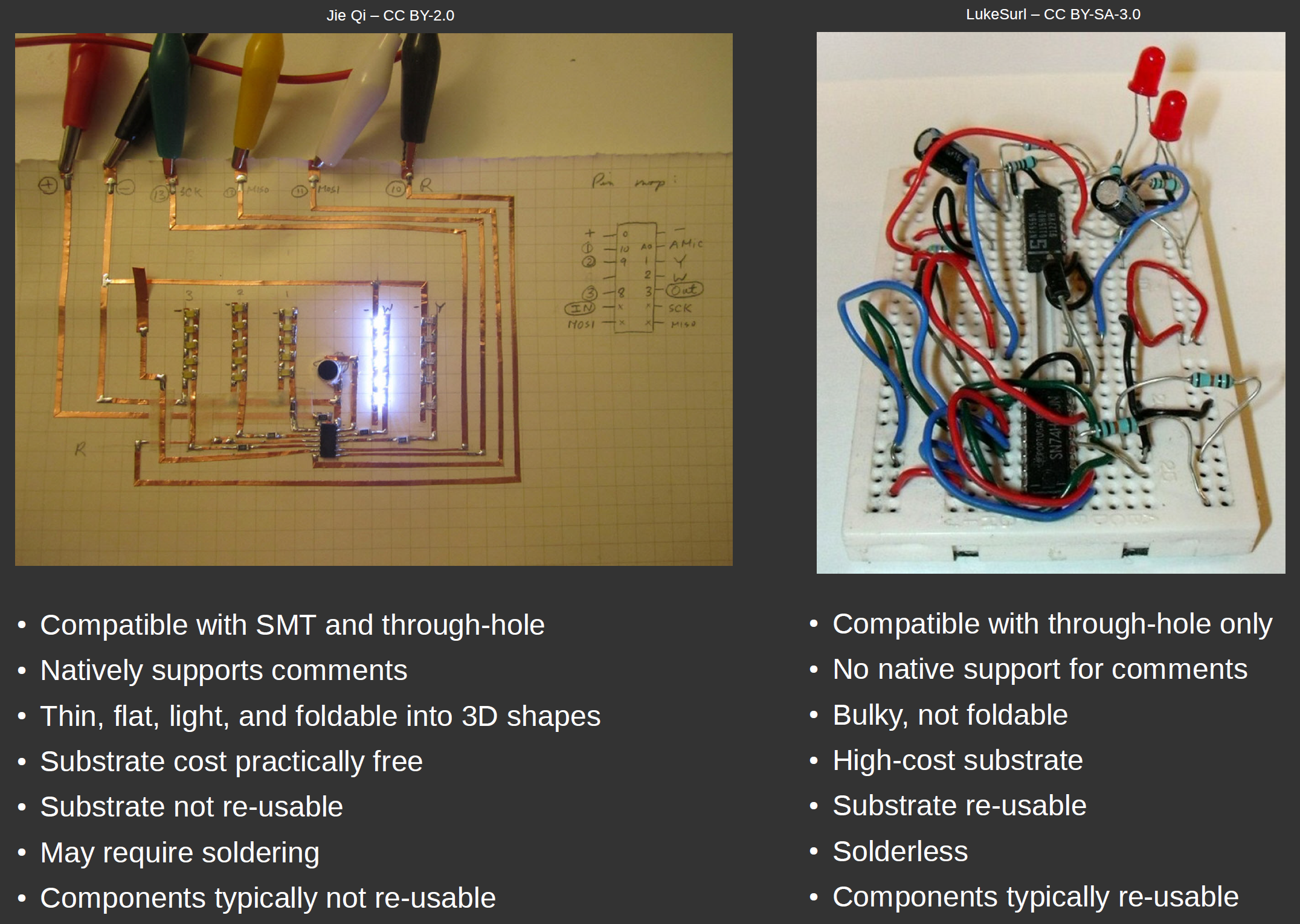
The second and perhaps more important advantage is that it’s electrically similar to a printed circuit substrate. Breadboards feature long, loose wires with no sense of impedance control at all. Printed circuits are 2.5-D (e.g. planar multi-layer) constructions that feature short, flat wires and often times ground planes that enable impedance control. Paper circuit construction is much closer to that of a printed circuit, in that flat copper tape forms traces that can be layered on top of each other (using non-conductive tape to isolate the layers). Furthermore, when laid on top of a controlled-thickness substrate such as cardboard, the reverse side can be covered with a plane of copper tape, thus allowing for impedance control. The exact same equations govern impedance control in a paper circuit constructed with a ground plane as a printed circuit constructed with a ground plane – just the constants are different.
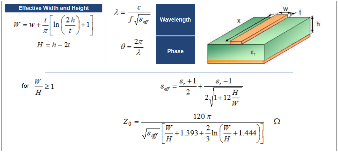
This equation works for both FR-4 and cardboard. Just plug in the corresponding ε, w, t, and h. From rfcafe.com.
This means you can construct RF circuits using paper electronic techniques — from directional couplers to antennae to amplifiers. The low parasitics of copper tape also means you can construct demanding circuits that would be virtually impossible to breadboard, such as high-power switching regulators, where ripple performance is heavily impacted by parasitic resistance and inductance in the ground connections.
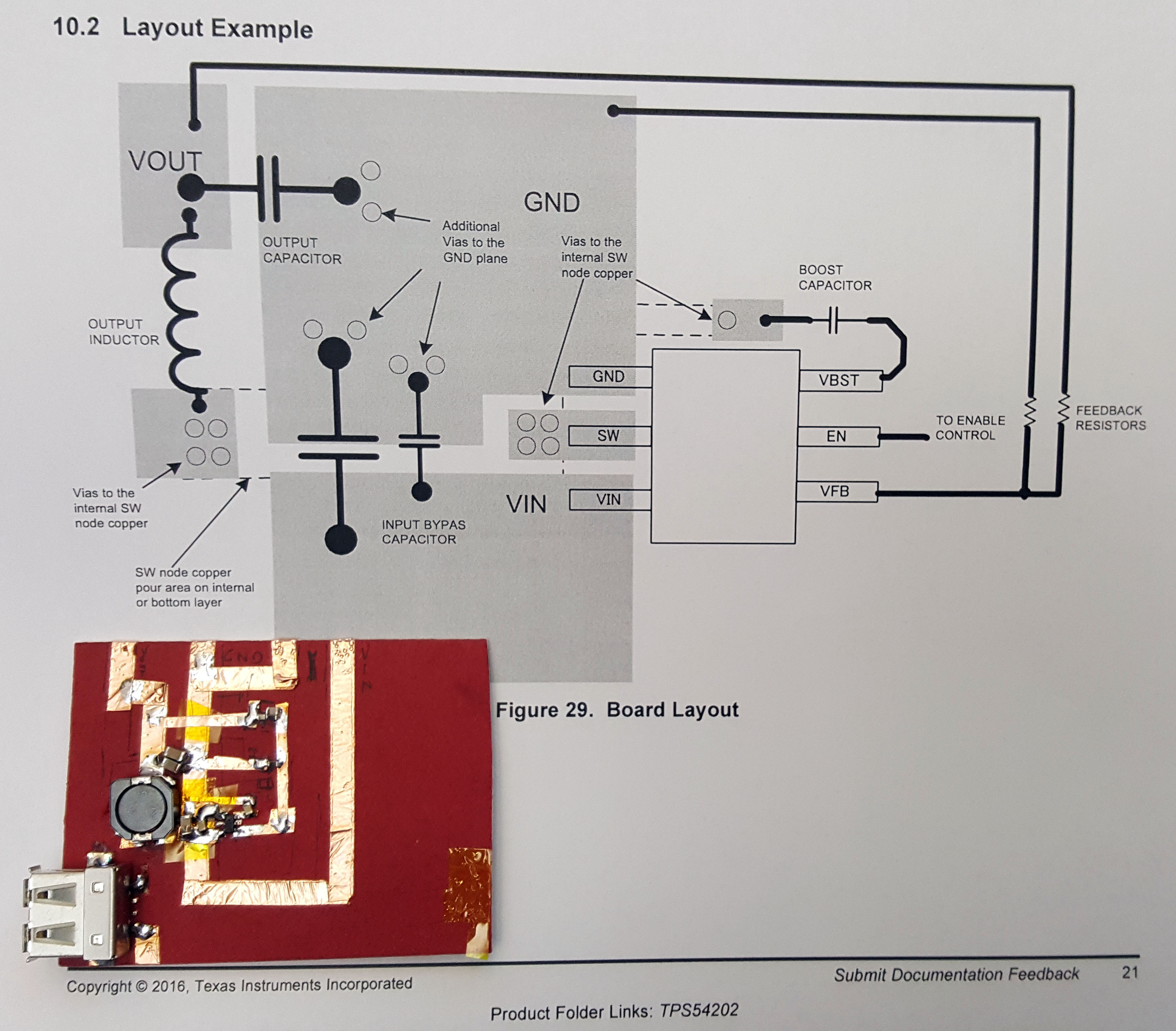
A 10W, 5V buck regulator laid out with paper electronics. The final layout closely resembles the datasheet layout example and performs smoothly at 2A load; this circuit probably wouldn’t regulate properly at high loads if built with a SMT-to-DIP breakout and a breadboard.
In addition to impedance control and lower parasitics, the use of copper tape to form planes means paper electronics can push the power envelope by leveraging copper plans as heatsinks. This is an important technique in FR-4 based PCBs; in fact, for many chips, the dominant path for heat to escape a chip is not through the package surface, but instead through the pins and package traces.
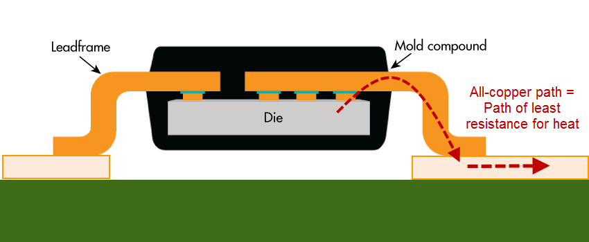
Copper conducts heat about 1000x better than plastic, so even the tiny metal pins on a chip can conduct heat more efficiently from an IC than the surface of the plastic package. Flip-chip on lead frame graphic adapted from Electronic Design.
The copper which forms the pins and lead frames of a chip package is a vastly superior (about 1000x better) heat conductor compared to air or plastic, so a cheap and effective method of heatsinking is to lay out a large plane of copper connected to the chip. Below is an example of a 60-watt power driver that I built using paper electronics, leveraging a copper tape plane plus extra foil as heat sinks.
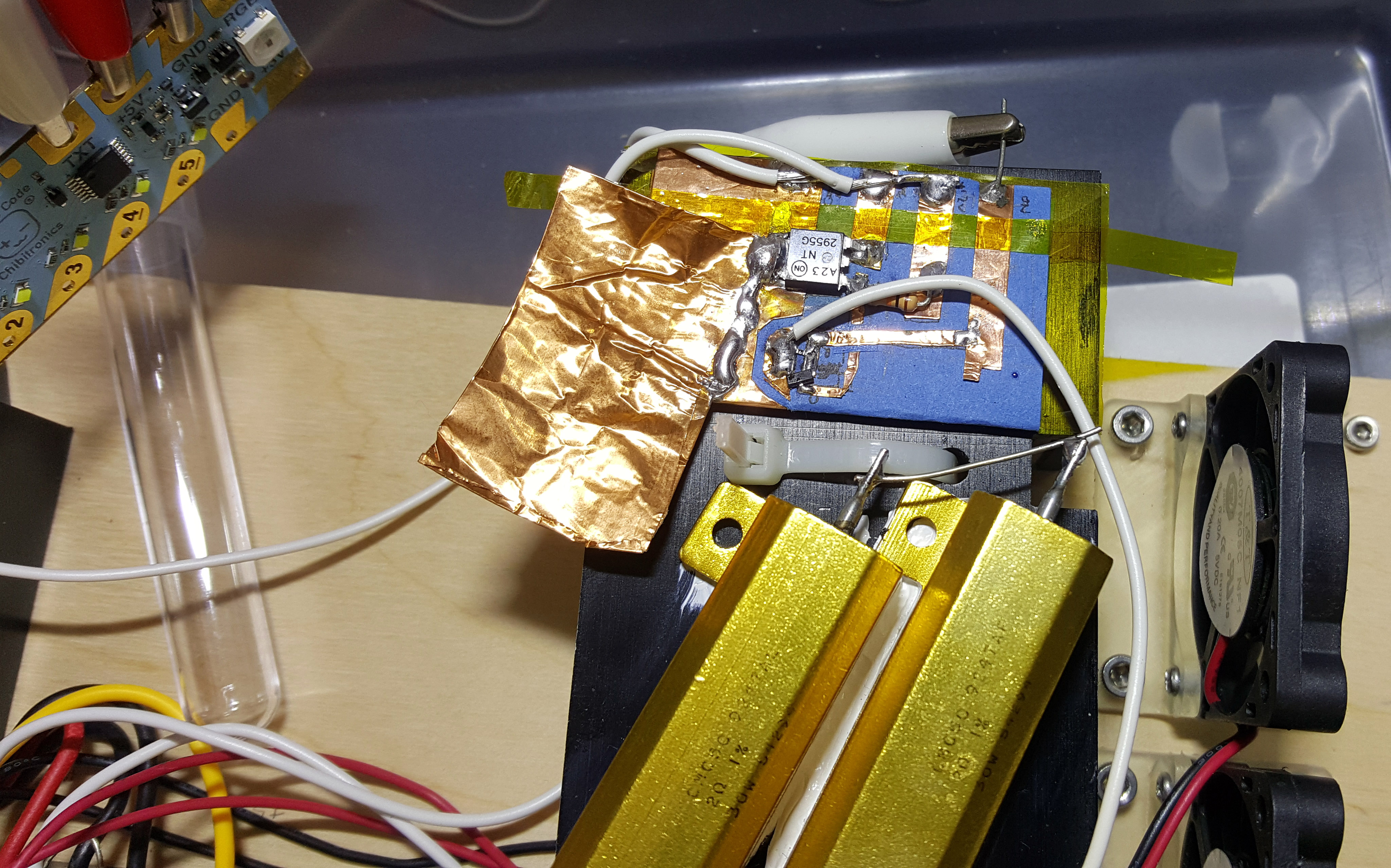
That’s a 12A power transistor, and this heater control circuit can use much of that ampacity. Additional copper foil was soldered on for extra heat sinking. The equivalent in DIP/TO packages might melt a breadboard during normal operation.
Paper electronics has one additional advantage that is unique to itself: the ability to fold and bend into 3-dimensional shapes. This is something that neither breadboards nor FR-4 circuit boards can readily do. Normally, circuit boards that can bend require more exotic processes like rigi-flex or flex PCB manufacture; but paper supports this natively. Artists take advantage of this property to create stunning electronic origami, but engineers can also use this property to great effect.
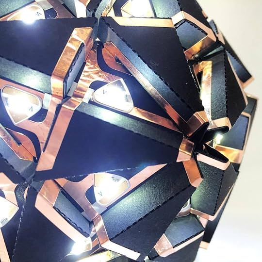
Trox Circuit Study 05 by Jonathan Bobrow, from the Paper Curiosities gallery
The ability to fold a sheet of cardboard or paper means that paper circuits can be slotted around tight corners and conformed to irregular or flexible surfaces, eliminating connectors and creating a thinner, sleeker packages. Need a test point? Cut a hanging tab out of your substrate, and you’ve got a fold-up point where you can attach an alligator clip!
Using Paper to Facilitate Prototyping with SMT
Here’s a detailed example of the construction techniques I use when working with paper electronics. I built a breakout board to solve a common problem: matching voltages between chips. Older chips are powered by 5V, newer ones by 1.8V or lower, and none of these are a match for your typical 3.3V-tolerante microcontroller. There are small circuits called “level shifters” that can safely take digital signals of one signal swing to another range. The problem is that most of the “good” ICs today come only in SMT packages, so if you’re prototyping on a breadboard or using alligator clips to cobble something together, you’ve got very limited options. In fact, one of my “go-to” ICs for this purpose is the 74LVC1T45; it’s capable of 420Mbps data rates, and can convert anywhere from 1.65V to 5.5V in a direction that can be selected using an input pin. The packaging options for this chip range from a DSBGA to a SOT-23 – clearly a chip targeted at the mobile phone generation, and not meant for breadboarding.
![]()
However, I’m often confronted with the problem of driving a WS281B LED strip from the I/O of a modern microprocessor. WS2812B LEDs operate off of 5V, and expect 5V CMOS levels; and no modern microprocessor can produce that. You can usually get away with driving a single WS2812B with a 3.3V-compatible I/O, but if you’re driving a long chain of them you’ll start to see glitches down the chain because of degraded timing margins due to improper voltage levels at the head of the chain. So, I’d love to have a little breakout board that adapts a SOT-23-sized 74LVC1T45 to an alligator-clip friendly format.
Instead of laying out a PCB, fabbing a one-off, and soldering it together, I took a piece of cardboard and built a breakout board in under an hour. Furthermore, because I can bend cardboard, I can make my breakout board dual-purpose: I can add pins to it that make it breadboard-compatible, while having fold-up “wings” for alligator clips. Without the ability to fold up, the alligator clip extensions would block access to the breadboard connections. Below are some shots of the finished project.

Native comments plus on-board decoupling caps makes this simple to use, even with long alligator clips
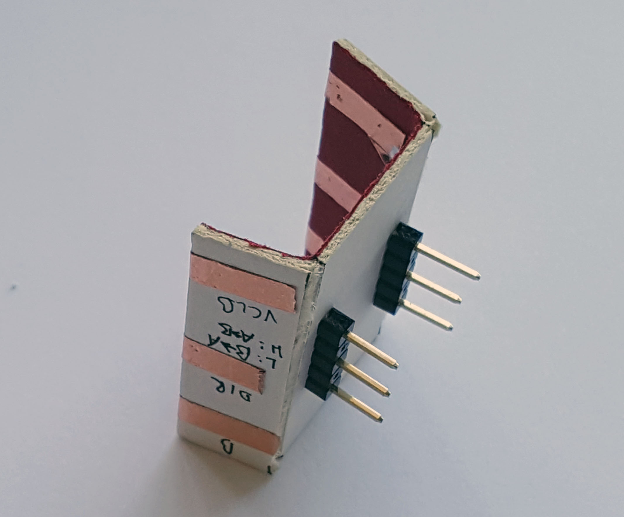
DIP pins coming out the bottom side allow this to be used in a breadboard, too
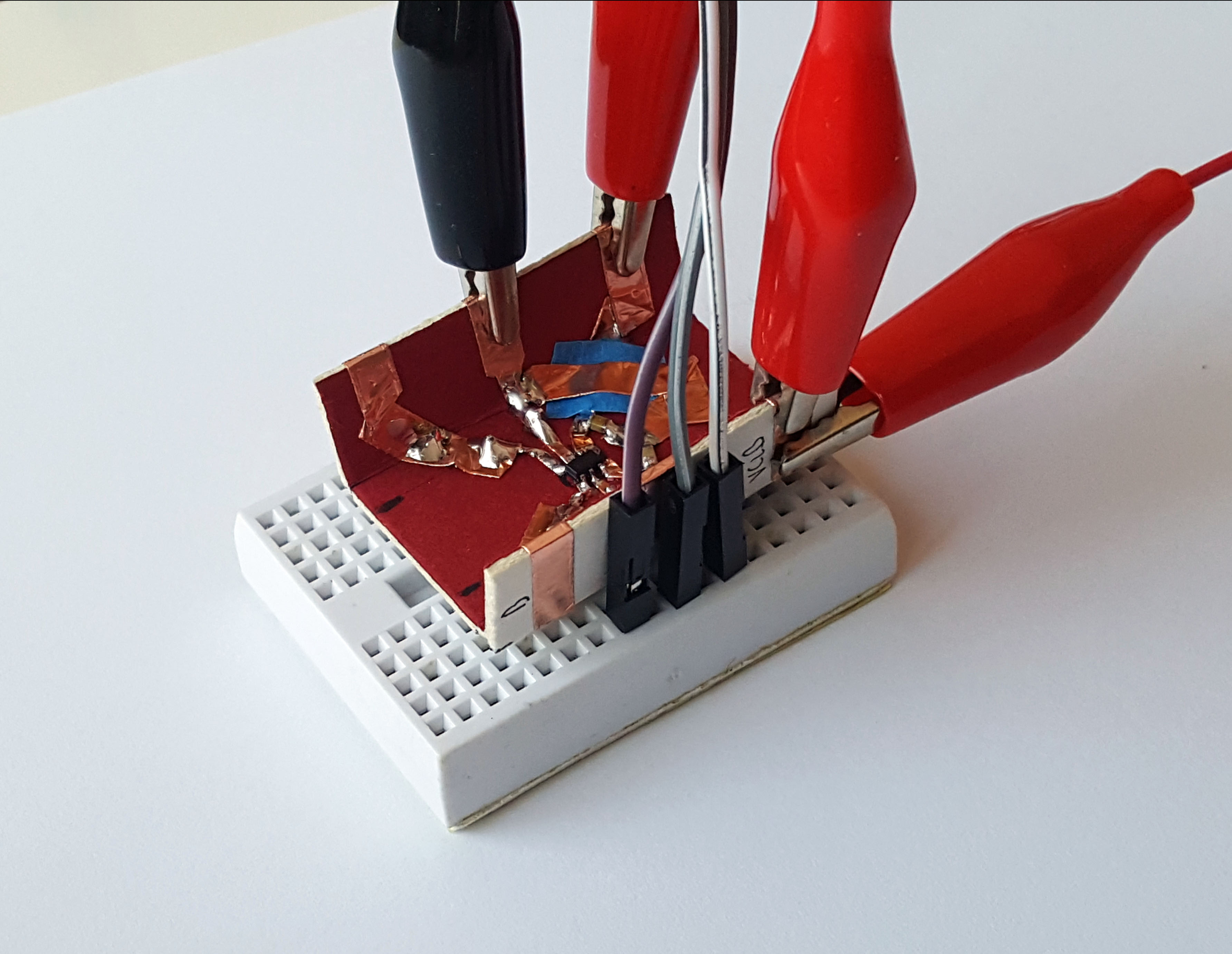
SMT, DIP, and alligator clips all coexisting in a single breakout — easy to do with paper!
The first step in making a paper circuit is to grab a suitable piece of cardboard. I’ve come to really enjoy the cardboard used to make high-quality mats for picture framing. It’s about 1.3-1.4mm thick, which is fairly similar to FR-4 thickness, and its laminate structure means you can score one side and make accurate folds into the third dimension. The material is also robust to soldering temperatures, and its dense fiber construction and surface coating keeps the paper surface intact when pulling off mild adhesives, like the ones found on copper tape.
I’ll then cut out a square about the size I think it needs to be. I’ll usually cut a little larger, because it’s trivial to trim it back later on, but janky to tape on an extension if it’s too small.
Then, I lay the components on top and sketch a layout – this one’s pretty simple, I just note where I want the SOT-23 to go, and where the breakouts should run to.

Once I’m happy with the sketch, I’ll lay down copper tape, solder on the components, and then fold/bend the breakout into the final shape.
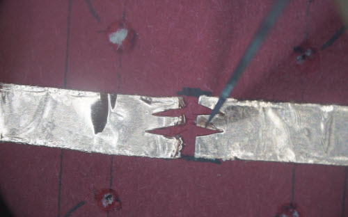
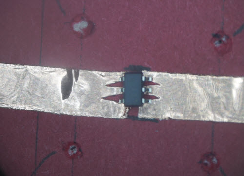
The trickiest and most important technique to master is how to mate the copper tape to the tiny pins of the SOT-23 (or other SMT) package. I use a trick that Dr. Jie Qi taught me, which is to cut a set of triangular notches into the tip of a wider piece of copper tape of roughly the right pitch. The triangular shape lets you adjust the size of the landing pad by simply changing the gap between the two ends of the tape, alleviating the need for precise alignment. Then, once the component is soldered to the wide piece of copper tape, you take a knife and cut the tape into individual traces – voilà, an SMT breakout is born!
A lot of this is better shown not told, so I’ve created a little video, below, that walks you through the entire process of building the breakout.
Try Something Different, and You Might be Rewarded!
Paper as an electrical engineering material is something I would never have thought of on my own – I grew up prototyping with breadboards and wire-wrap, and I was prejudiced against paper as a cheap, throwaway material that I incorrectly thought was too flammable to solder. Instead, I spent hundreds of dollars on breadboards and wire wrap sockets, when I could have made do with much cheaper materials. Indeed, there is an irrational psychology that regards expensive things as inherently better than cheap things, which means cheap options are often overlooked in the search for solutions to hard problems.
But this is why it’s important to collaborate with experts outside your normal field of expertise – the further outside, the better. In addition to being a great engineer, Jie Qi is a prodigious artist. Through our Chibitronics collaboration, she’s added so much more depth and dimension to my world on so many fronts. She’s imparted upon me invaluable gifts of skills and perspectives that I would never have developed otherwise.
It’s my hope that by sharing a little more about paper electronics, I can bring a fresh perspective on old problems while broadening awareness and getting more users to improve upon the basics. After all, this is a new area, and we’re just starting to explore the possibilities.
Interested in hacking paper electronics? Check out the Chibitronics Creative Coding Kit, and the Love to Code product line. It’s a gentle introduction to paper electronics targeted at newcomers, but it’s also open source, so you can take it as far as your imagination can go — hook up a JTAG box, build the OS, and get hacking! Get 30% off the Creative Coding Kit with the TRY-LTC-18 coupon code until June 30, 2018!
Quick edit: some basic techniques on using copper tape are documented at Chibitronics’ Copper Tape Chronicles. It’s a small compilation of videos like the one below:
Also, here’s a handy tip on how to keep copper tape from falling off the roll:
April 23, 2018
Name that Ware, April 2018
The Ware for April 2018 is shown below:
It’s a simple ware, but you could say I’m rather personally attached to it. Prize to the funniest/most creative story about this ware :)
Winner, Name that Ware March 2018
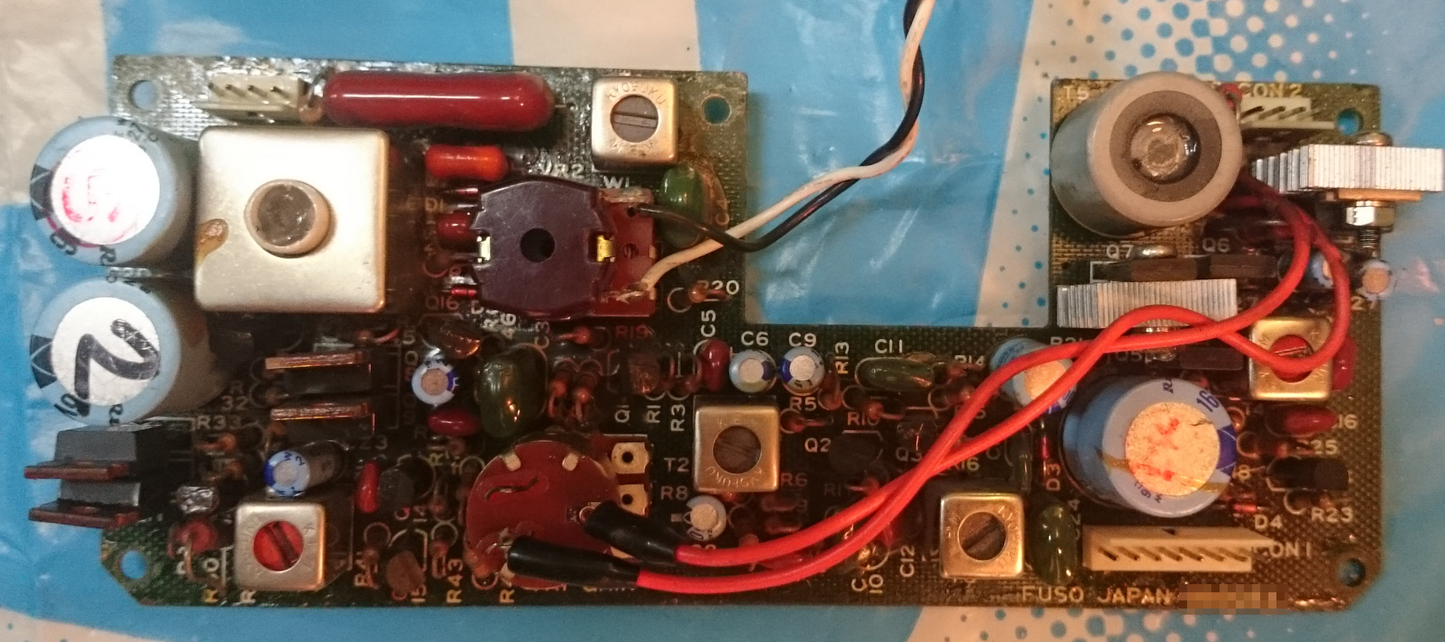
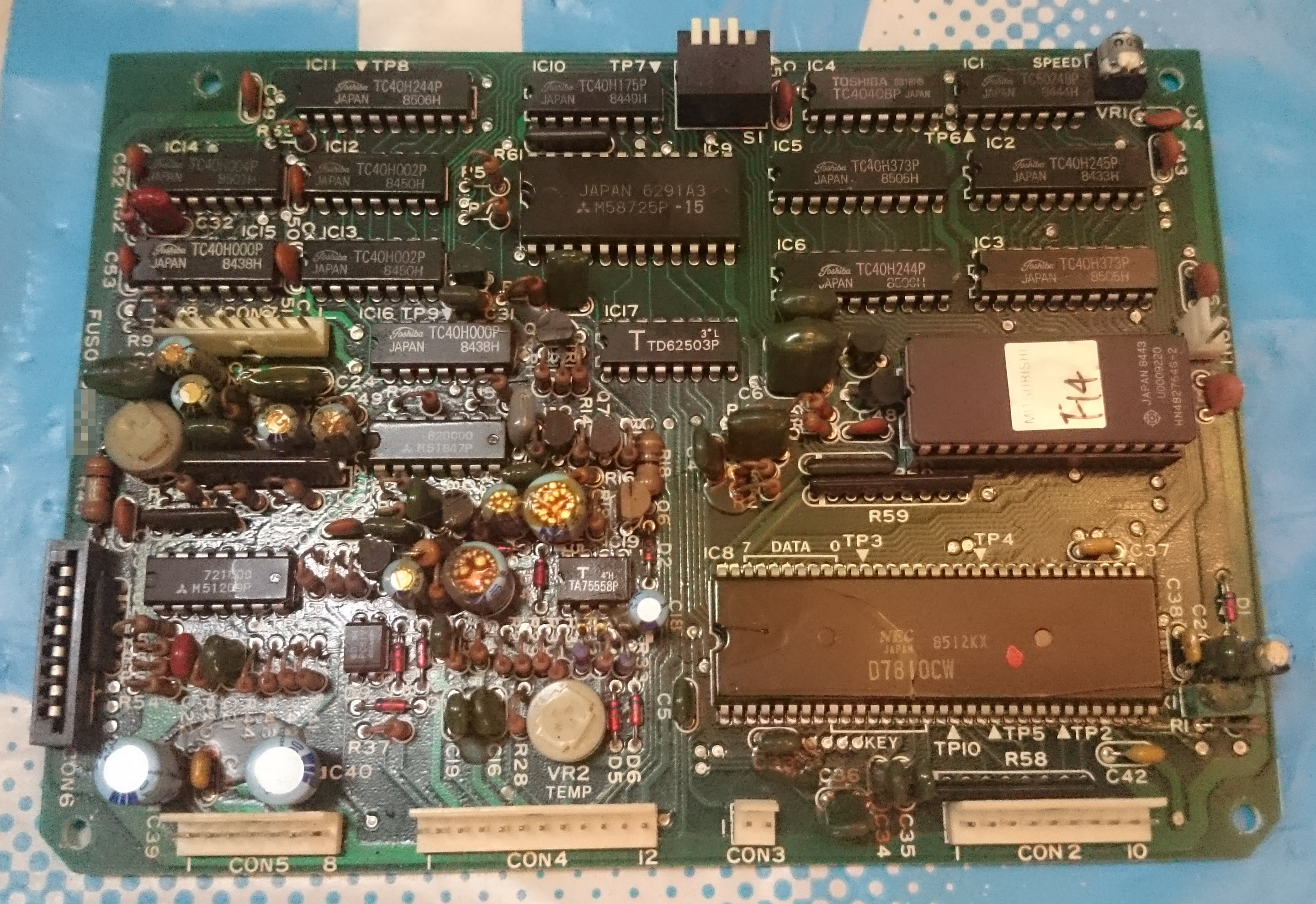
The Ware for March 2018 is a Fuso 150 Fish Finder. Mangel hit the nail on the head with this guess — excellent work, as always! email me for your prize :)
March 31, 2018
Andrew Huang's Blog

- Andrew Huang's profile
- 32 followers

