
Andrew Huang's Blog, page 14
June 29, 2021
Name that Ware June 2021
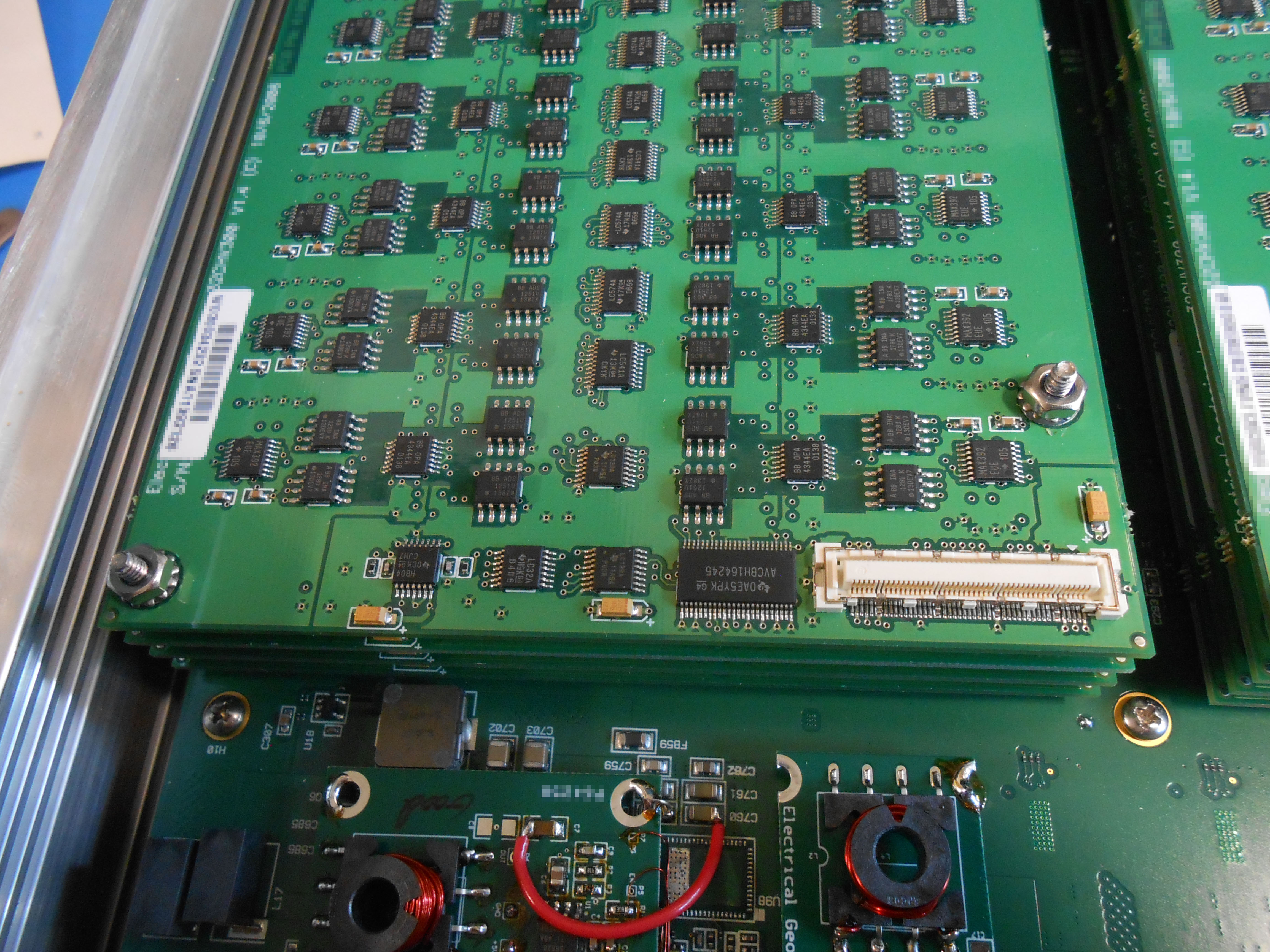
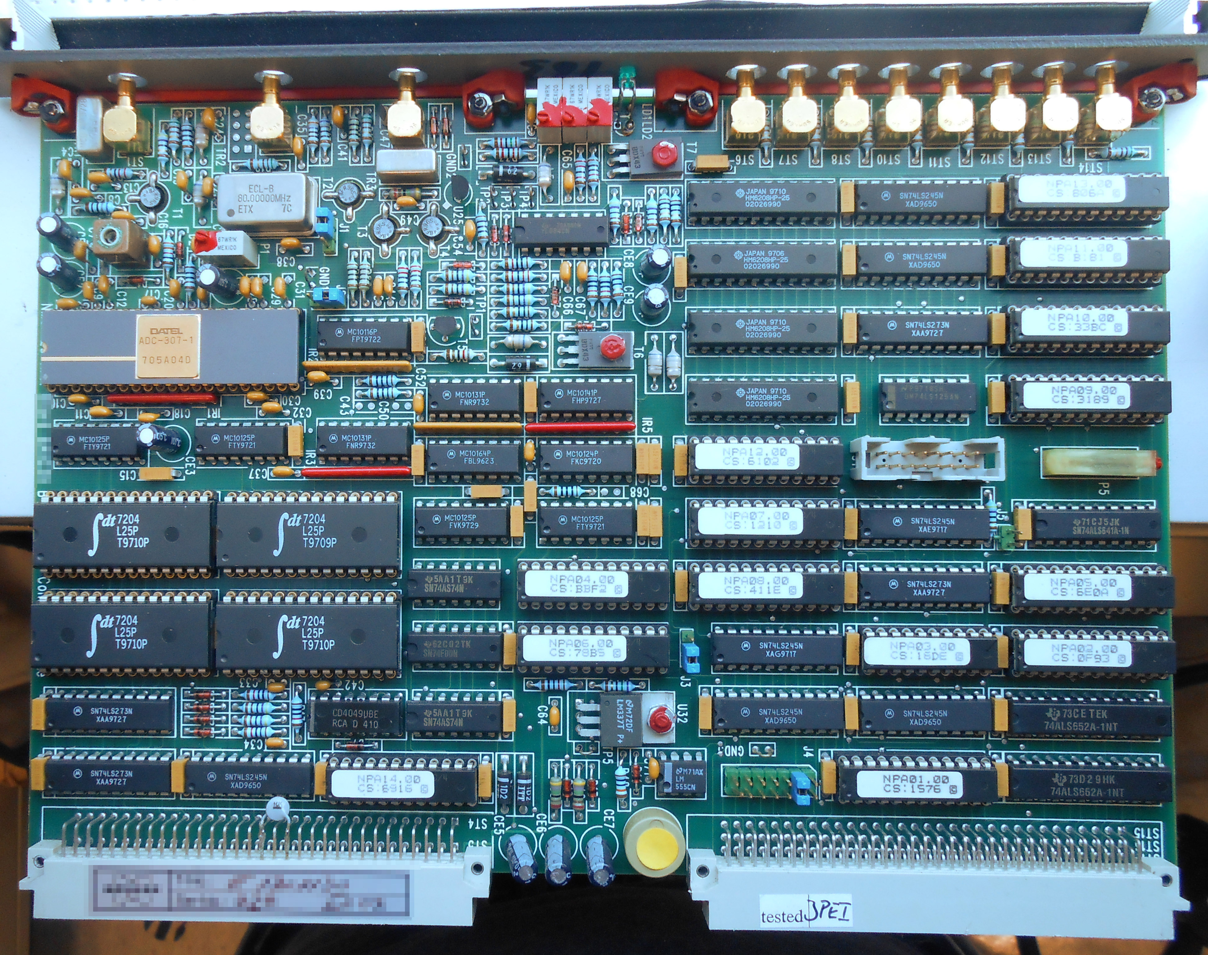
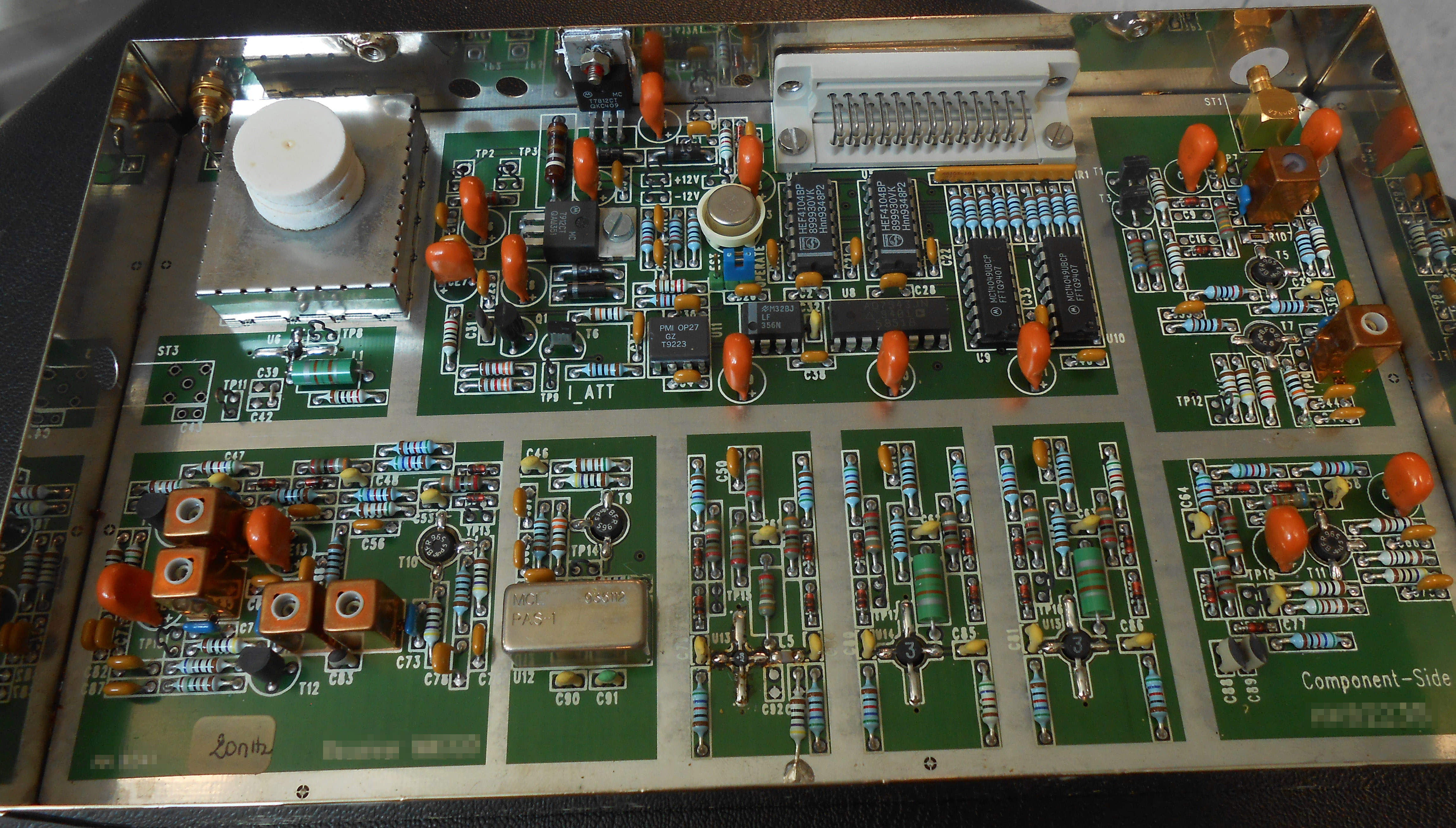
The Ware for June 2021 is shown below.
This is, I think, the last from the Don Straney collection (thank you so much for helping to bridge me through the pandemic!). Maybe I’m showing a bit too much here to make it hard to guess, but, honestly, I had never seen the inside of one of these types of things before, and I probably never will in person; so I wanted to share more than less of its construction details. It’s kind of crazy what a rat’s nest it is on the inside; I particularly love the tiny loops of wire which I’m pretty sure are meant to serve as inductive elements, and not just jumpers.


Winner, Name that Ware May 2021
For email subscribers, apologies in advance if you get two copies of the Name That Ware post series this month — I’m still trying to sort out some new email client configurations. I’m guessing it’ll take a few tries before everything works right.
On to the Ware — looks like I left a little too much text in on this one! Taylan Ayken got the exact model and make, a 256-channel Net Amps 410 from Electrical Geodesics. Congrats, email me for your prize!
Whenever you hear things like “256 channels” these days it’s easy to assume it has to be all integrated into a single chip. But, then you come across gems like these and you’re re-assured that the technique of the board-level integration of hundreds of channels is still alive and kicking, despite the best efforts of Moore’s Law to integrate everything into a single epoxy blob.
June 25, 2021
Email Subscription Plugin Migration
Sorry for this bit of administrivia — apparently, Feedburner, which I have been using for years to serve email subscriptions, is ceasing the email service in a couple of weeks. My first instinct was to just trash the service altogether, but I was pleasantly surprised to see I had a not-small number of email subscribers. So, instead of just trashing the feature I’m attempting to do a graceful migration.
Unfortunately, I’m not well-qualified to configure an email plugin for WordPress — social media is about fifty abstraction layers above my comfort zone of solder and assembly language. It doesn’t help that if you try to Google “email subscription plugin WordPress” you are assaulted by a long list of low-quality but highly SEO-optimized and/or promoted suggestions, many of which seem downright sketchy. So, based on nothing more than the number of installs and the appearance of an active maintainer/developer, I picked the Icegram plugin to try and manage email subscriptions from here forward.
I’m hoping existing subscribers barely notice any change, and of course, feel free to unsubscribe if you find anything annoying — the last thing I want to do is to spam anyone.
But, it seems email plugins have gotten far too crafty about by far too many things. If anyone has any advice on how I could handle this transition better or if anyone notices this plugin doing something strange or privacy-invasive, drop a comment here and I’ll try to figure things out. I’m not going to learn PHP and CSS to fix cosmetic annoyances like the improperly sized email sign-up field on Firefox…but I’d rather trash email updates altogether than invade a not-small number of people’s privacy.
Running a blog was so much simpler twenty years ago…
June 22, 2021
Adding a ChaCha Cipher to Precursor’s TRNG
This is the second post of a two-part series on Betrusted/Precursor’s True Random Number Generator (TRNG).
A bulletproof source of random numbers is a key component of any cryptosystem, so we’ve done an extensive, months-long characterization of Precursor’s dual, redundant TRNG sources, which consists of an avalanche noise generator and a ring oscillator. We’ve found them to produce passable raw entropy, but you don’t have to take my word for it. You can download our raw data and run your on analysis on it if you like (at least until our ISP cuts us off for serving multiple 10GiB files filled with random data).
However, the system is still missing two features that are generally considered to be best practice:
Independent, on-line health monitors of the raw TRNG outputs, discussed in our previous post.Conditioning of the raw data.Because Precursor uses an FPGA for its SoC, we can add new features to the hardware “on the fly”, and in this post will focus on adding the hardware for the conditioning of raw data. The post is a bit of a slog to read through; I’ll try not to do too many in this style. But occasionally, I think it’s good to have a “reality check” that conveys the depth of difficulties encountered while implementing a feature, instead of making everything look easy or cramming all the details into a tweet. This post will hopefully also serve as a detailed reference for the handful of future developers who want to implement similar features, and would like to avoid some of the mistakes I’ve made.
Despite best efforts to make TRNGs unbiased and flawless, they are really hard to get right. Furthermore, they are only capable of producing high-quality entropy at a limited data rate. Thus, most practical systems take a TRNG output and run it through a cryptographic stream cipher to generate a final datastream; this conditioning of the raw data simultaneously protects against minor flaws in the TRNG while improving the availability of entropy.
So in Precursor, we’d like to add some conditioning on the collected entropy. To be clear, we will always make the raw entropy pool available for inspection — this is absolutely necessary for testing and CI coverage — but it’s a good idea to throw the output of your TRNG into a cryptographically sound stream cipher of some type, so that in the case that your TRNG suffers a sporadic drop-out, you don’t have a disastrous, instantaneous collapse of entropy. Depending on how you configure the conditioning, you can also increase the effective availability of random numbers.
After poking around a bit on the Internet, it seems popular to feed a seed of entropy into the ChaCha20 stream cipher (I refer to it as a “cipher” in this post, but I think more technically because of the way I’m using it, it should be referred to as a CSPRNG – Cryptographically Secure Pseudo Random Number Generator). This is done in the Linux kernel as well as by cryptech.is’s HSM and a few other implementations. The devil, of course, is always in the details. Cryptech.is takes the output of their TRNGs, hashes them with a SHA2 block, and then feeds it into a ChaCha20 stream cipher. Linux maintains an entropy pool that is collected from a variety of low-and-high-quality sources, blends them using some fast and slow techniques based upon the nature of the source, runs it through SHA1, and then into ChaCha20 to create the final stream.
In our implementation, we’re skipping the SHA pre-hash of the entropy pool, for the following reasons:
We don’t have the space (as in FPGA gates) or computational resources (as in CPU cycles for software emulation) to do this continuouslyThe raw entropy sources themselves are fairly high-quality (as opposed to in the case of Linux they are taking things like time stamps and network traffic patterns, so using SHA-1 to blind that is quite reasonable); and, we have two entropy sources of different architectures, each source consisting of multiple raw entropy generation elements. In other words, we’re starting from a pretty good place already.The ChaCha20 cipher is mainly to protect against transient drop-out or unpredicted aging issues in the TRNG.The ChaCha20 cipher itself is considered to be cryptographically secure; augmenting it with a SHA pre-hash does not seem to lend any clear benefit in our case.We will prefer to reseed the ChaCha20 cipher at a fairly high rate, rather than seed it occasionally through a more expensive SHA operation.Also in reading some of the docs out there, it seem that 20 is the minimum number of rounds considered to be cryptographically secure for ChaCha, but “more rounds is better”. Thus, while tweaking the Secworks open-source Chacha implementation to fit in Precursor, I think I’ll also create an option to let the ChaCha rounds function run to at least a minimum number of rounds but otherwise “free run” when the system is idle. This makes it useless as a cipher, but if the power impact is minimal, this should help the diffusion of entropy across all the bits of the cipher and make it more robust against attempts to back-track its state.
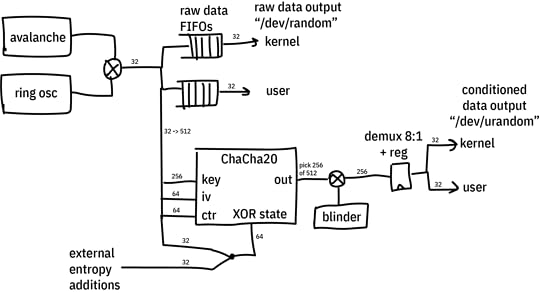
The diagram above gives a general idea of the architecture of the system. Not shown is logic that ensures the ChaCha20 cipher has completed its minimum amount of rounds between each output sample, and automatic re-seeding logic that pulls in 32 bits of entropy from the TRNGs on a regular basis at some re-seeding interval that can be programmed by software.
After installing the tooling necessary to build a Precursor/Betrusted SoC and run simulations, I started writing the code.
Here’s the general method I use to develop code:
Think about what I’m trying to do. See above.Write the smaller submodules.Wrap the smaller modules into a simulation framework that shakes most of the skeletons out of the closet.Repeat 1-3, working your way up the chain until you arrive at your full solution.Write drivers for your new featureSlot your feature into the actual hardwareTest in real hardwareContinuously integrate, if possible, either by re-running your sim against every repo change or better yet recompiling and re-running your test on actual hardware.The key to this loop is the simulation. The better your simulation, the better your outcome. By “better simulation”, I mean, the less assumptions and approximations made in the test bench. For example, one could simulate a module by hooking it up to a hand-rolled set of Verilog vectors that exercises a couple read and write cycles and verifies nothing explodes; or, one could simulate a module by hooking it up to a fully simulated CPU, complete with power-on reset and multiple clock phases, and using a Rust-based framework to exercise the same reads and writes. The two test benches ostensibly achieve the same outcome, but the latter checks much more of the hairy corner cases.
For Betrusted/Precursor, we developed a comprehensive simulation framework that achieves the latter scenario as much as possible. We simulate a full, gate-level VexRISCV CPU, running a Rust-built BIOS, employing as many of the Xilinx-provided hardware models as we can for things like the PLL and global power-on reset. You can make a new testbench by running the “new_sim.py” script in the `deps/gateware/sim` directory, and it will automatically copy over all the basics so you can just instantiate your core module and start running simulation code.
Another thing I learned perhaps too late was to pick a good IDE. Python sucks to develop. It sucks even more without an IDE. For a long time I was writing in vanilla emacs. The game-changer for me was being able to control-click through modules and find their definitions; most IDEs support this.
Writing The BlockI noted in Cryptech.is’s presentations that they were using a 24-round variant with a potential to go to 32; and even though cryptanalysis shows its solid with 20 rounds, perhaps there is still a potential that maybe some knowledge of the output could be used to infer something about the next set of outputs.
So, I still made a very light-fingered change, where the core round function could be advanced by one during idle periods based on a `force_round` input. In any case, the output of the ChaCha cipher is not used until at least 20 rounds in any case, but on average it will go many more rounds (thousands of rounds) before the output is used, and the number of rounds advanced depends upon the exact timing of the code that accesses the TRNG.
Thus, the overall flow of events for the conditioning block are as follows:
On boot, we pull in 384 bits of “key” state (256 bits key + 64 bits iv + 64 bits nonce) from the TRNG, and then initialize the cipher.We also pull in 512 bits of “input” state. This is a fixed quantity that is XOR’d with the ChaCha block state. I worry that tying this to a fixed value could lead to leakage of the ChaCha state to the output, thus, on every boot we load in a new random input value.Once the cipher is initialized, a counter keeps track of how many blocks we’ve generated. Once we have passed a threshold, the conditioner automatically requests another 32-bit word of entropy from the TRNG and does a rotate-and-XOR of the data into the “key” state. The key state is re-incorporated on the next “advance” call of the block.Every “selfmix” interval, the cipher will also advance its rounds counter by one (this is the supplemental entropy/scrambling as noted previously)The user can also supply seeding data at any time, which is folded in with a rotate-and-XOR function. Note for every seed provided, it’s best practice to read 16 words of TRNG output, to ensure that the seed state is incorporated into the TRNG as a whole. It doesn’t harm things to not do that, just, if you kept on applying the same seed over and over again it’ll eventually just XOR into and out of the key pool without doing anything useful.The output of the cipher is latched into a 512-bit register, and `urandom` data outputs are multiplexed to the kernel and userspace through the CSR. A `valid` bit is provided, and it should be checked prior to every read of data from the Conditioned TRNG output.Building, and FailingSo your code is all writ, now time to try a quick “smoke test” to see if the build fails. And, sure enough, even though the build completes, I’m not meeting timing. We’re using a -1L variant of the Spartan 7 part, which is the lowest power model (important for battery life) but also the slowest performer in the group. So, even though Cryptech.is advertised hitting 100MHz performance on the block, I did note they were using a -3 variant (one of the fastest models) of a fairly high-end Artix FPGA.
So, back to the drawing board — it’s time to drop the clock frequency on the core to 50MHz. This is probably fine from a performance standpoint, as it could still yield 1.6Gbps burst rate of random numbers, but it does introduce some potentially thorny issues with clock domain crossings. In particular, I don’t get to be lazy and just use a bunch of Migen’s BusSynchronizer primitives to bridge 512-bit data between domains. That would be…expensive, in terms of logic resources. Instead, I’m going to have to be careful and use multi-cycle paths with explicit timing exceptions to make sure this works and without consuming undue amounts of resources.
What — you mean you thought getting code to compile was the end of the story? In hardware, every flip flop is a race condition against a clock — just think of it that way. Every time you make a register, you now have a potential concurrency problem. Now scale that up to the tens of thousands of registers in an FPGA, and you get an idea of why correct compilation is only a small portion of the whole story.
Failing More, in Order to Get BetterAfter reducing the frequency of the core to 50MHz and fighting for a half day with the Vivado constraints syntax to convince it not to spend half an hour routing cross-clock-domain that are actually relaxed, I finally have the design building with timing closure. The next step is going back into the simulation bench and checking all the corner cases.
I modified the existing `trng_managed` simulation bench to add a series of tests that would exercise all the new features — including checking the rate of read, all the dual port options, and deliberately forcing some reads to fail by bypassing certain checks on validity of data to really push the engine to its limit. In the process of running these benches, I found more new corner cases, for example, the ChaCha engine would stall if the raw entropy FIFO ran out of seeding data; it would just wait for reboot of the avalanche+ring oscillator TRNGs, a process that can take milliseconds. This shouldn’t happen on the `urandom` engine — it is the “unlimited” random data engine after all, so some fixes were made to keep the block state evolving even if we ran out of seeding data. However, I have to emphasize this really is a corner case, you have to basically configure the system to constantly reseed and pull entropy out at a rate much higher than you can do anything useful with it to hit that limit. But, that’s the point of testing — to break your system before users do.
Rinse, Lather, RepeatNow that the simulation runs, we repeat the loop and see how badly timing is broken. It turns out with all the tweaks in place, I’ve introduced an accidental critical path. While the design can meet timing with this, it takes almost 3x the time to build, which means we’re probably going to start failing builds pretty soon. I should probably fix this problem now, while the design details are fresh in my head.
I open up the design in the Vivado tools and have it plot a timing histogram for me, below is an example of the output:
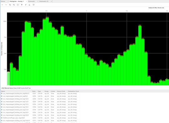
Above: Example of a slack histogram generated by Vivado. Green bars toward the left indicate paths with less timing slack, to the right have more. So for example, the left-most bin has 206 paths with 0.041ns-0.227ns of slack. The more “left-heavy” the histogram is, the harder the design is to place & route, and the more likely the process will not complete with perfect timing closure.
The left-most bin are the most over-constrained elements, and I can see that the `trngmanaged_holding_buf` registers are just barely passing.
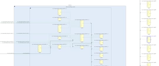
I generate a schematic view like this inside the Vivado design tool, and backtracing the inputs to the `holding_buf` registers I can see the signal eventually goes through an enormous combinational path that includes the VexRiscV’s address decoders. This means that we have a critical path that extends from inside the VexRiscV load/store unit all the way to the 512-bit shifter of the ChaCha block.
If it were the case that we actually needed to pull data cycle-by-cycle out of the ChaCha block and somehow change the behavior of the system within a single cycle, then this path would make sense. But in practice, the actual rate is far lower than that — the tightest, most unrolled read loops take at least 2 cycles to execute; but more typically 10-12 cycles per iteration if you’re doing any sort of useful load or store with the data and running it from a rolled-up loop. Furthermore, the ChaCha block is basically a “read-only” block — there’s nothing the CPU is going to do to reconfigure it on the fly that would prevent us from
pipelining this.
So, I go back and add a “depth 1 FIFO” to the output, to break the shift register out of the critical path while still preserving the read-invalidate semantics required by the CSR interface (that is, the contract we have with the CSR interface is the cycle after a random number is read, either the next value should be a valid, new random number; or it can be an invalid number, but the “valid” bit must be cleared that very cycle). Using a simple pipeline register won’t work, because it introduces an extra cycle delay on the read-invalidate semantics and it’s possible, although very unlikely, that a code loop could have back-to-back loads and it will grab a stale “valid” state.
After running another simulation just to make sure we haven’t introduced any new bugs, I run a compilation again and hope this greatly relaxes the timing. It didn’t, but long story short, I had accidentally leaked one path in the FIFO through as a combinational element. After spending a couple hours tracing that issue out, I finally met with some success.
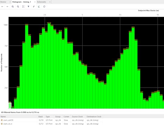
After applying these fixes, the compilation time is back down to its normal value, and we can see that the timing bins at the very far left of the histogram have a fraction of paths as before — 69, down from 206. It looks like the `holding_buf` register is still causing some troubles, but at least we’ve taken pressure off of the actually most difficult paths, which are inside the Curve 25519 Engine, and not some made-up timing emergencies inside the shift register at the output stage of the TRNG.
The price of all the timing fixes is increased resource utilization. Initial estimates showed about a 6% area cost for the ChaCha block without the timing fixes, but we ended up with around 10.5% area cost once all is said and done. The SoC uses around 68.2% of the FPGA now, which is still fine for routability and gives some space for a few more smaller blocks, but it’s probably at the upper limit of what we can reasonably expect to fit while having short (~8-9 minute) compilation cycles. I’m also making a mental note to myself that as part of the histogram analysis it looks like the next critical path to knock back is in the CSR address decoders. Adding the dozens of registers to read out the results from the TRNG health tests has probably forced an extra layer of LUTs to be instantiated inside the core arbitration logic; thus, pruning some of these registers if they end up being superfluous could be a way to win back some timing margin if I end up in a jam later.
Rubber, Meet Road. Road, Meet Rubber.Well, that took some time in simulation. But we’re not done yet! It’s time to run this code on real hardware, and then upgrade the kernel and services of Xous to use it — and let’s not forget CI integration as well.
First things first, let’s just take the design, as-is, with no mods to Xous and see if it boots, and what the power draw change is. The good news is that things boot, and the system draws about 5 mA extra, or about 5% more idle power than it did before. The ChaCha whitener is in the always-on domain, because it has to be able to run while the kernel is idling to produce random data. In particular, the core can “wake up” the avalanche generator and ring oscillators while the CPU is idle to summon more TRNG data even when the CPU is asleep; as such its clock can’t be gated off, but it is better than the alternative of running the CPU to manage these processes. A quick test tweaking the knobs on the duty cycle of the self-mixing for the ChaCha core shows it doesn’t have a measurable impact on the power, which means that probably most of the extra power is just the fixed cost of clocking that much more logic on the fabric.
The next step is to switch over the kernel and core services from using raw random numbers to the new ChaCha conditioned “urandom” source. This should have been easy in theory since everything worked in simulation, but of course — it didn’t work. I was greeted with a full system hang on the first go. This kind of bug is dreaded, because it’s some issue in the full system integration that exists outside of the testbenches, so you have to resort to long compile cycles and “printf” debugging.
Some further poking revealed that even worse yet, on some boots, the system worked, on others, it didn’t. However, the pattern was enough for me to suspect an issue in the reset logic. Going back into my code, I did find a subtle bug where I forgot to assign the reset line for the ChaCha core to the 50MHz clock domain (it was still tied to the reset for the 100MHz clock domain). For good measure, I also added a reset pulse extender, just to make sure it saw a long, solid reset. The polarity of the ChaCha core reset is opposite from what the rest of the system uses, so it’s also possible there is some glitches due to that. Anyways, after another four hours of tweaking and testing these fixes, re-running simulations, and cross-checking documentation about the reset process to really make sure we found a root cause, the system seems to come up as expected from the “urandom” source.
For TRNGs, The Work is Never DoneThe final phase of modifying any TRNG is continuous integration. This is extremely important because you can only get a hint if a TRNG is mis-behaving in subtle ways after collecting dozens of gigabytes of data from it over dozens of runs; and due to the limited rate of entropy, gathering such quantity of data can take weeks. Thus, we have a Precursor unit dedicated to doing nothing but rotating through its entropy sources and feeding its data into a set of test suites to try and uncover any subtle biases in the generators. You can browse the raw data and results of our CI bench here.
Now that we have this conditioned output, we need to integrate that into the test bench. It’s also going to be important to do a few “cold boot with recorded data” runs as well, so we can compare boot-to-boot to make sure that we have actually seeded the generator with random data and we’re not just accidentally running a ChaCha cipher (which should have excellent statistical randomness) with a fixed set of keys (which would have an identical stream boot-to-boot despite the excellent statistics).
In the process of re-integrating these tests into the CI bench, I discovered a number of problems with our original tool for shuttling random numbers to the host for analysis. For a number of reasons, the original CI tool relied on a fairly complicated Rust program with multiple threads, which was getting hard to maintain and the Rust wasn’t adding a lot of value; in fact I found a subtle integration bug that was causing all the tests for the past month to be run only on the ring oscillator!
Since we had a pretty decent Python script for doing USB updates over USB, I modified that into a script currently living in xous-core/tools/trng_test.py. This script is matched to a thread that runs inside the `trng` server on the Xous side when it is built with one of the TRNG tester options. On the Precursor side, a pair of 512kiB buffers are filled and the host is told which of the two to read from. The host-side Python script then reads the buffers and echos its contents out as binary data to stdout, which can then by piped into an analysis program (such as `dieharder`) or recorded to disk for later analysis. This whole mess is then wrapped in some other shell-script Frankenstein that’s fired off by a cron job which manages the rebuild, reflashing, and logging of data via a Raspberry Pi that can keep an eye on the serial console for errors during the CI process. It feels like a house made of playing cards, but it works!
Closing ThoughtsIf you made it this far, congratulations. Hopefully it conveys, with some accuracy, the range of difficulties one might encounter when implementing a “typical” feature like this for an FPGA-based SoC, and it may even be useful to the handful of developers who want to actually attempt something like this!
June 14, 2021
Monitoring the Health of Precursor’s TRNGs
This post is an abridged version of a longer-form narrative on implementing health monitoring for Precursor/Betrusted’s TRNGs. It’s the first of a series of two posts; the second, on implementing a CSPRNG conditioner for the TRNG, will go up later.
BackgroundOnline health monitors are simple statistical tests that give users an indication of the quality of the entropy being produced. On-line health tests are like a tachometer on an engine: they give an indication of overall health, and can detect when something fails spectacularly; but they can’t tell you if an engine is designed correctly. Thus, they are complimentary to longer-running, rigorous diagnostic tests. We cover some of these tests at our wiki, plus we have a CI bench which generates gigabytes of raw entropy, over runtimes measured in months, that is run through a series of proofing tools, such as the Dieharder test suite and the NIST STS test suite.
It’s important that the health monitoring happens before any conditioning or mixing of the raw data happens, and significantly, there is no one-size-fits-all health monitor for a TRNG: it’s even advised by the (NIST SP 800-90B sec 4.4) specification to have tests that are tailored to the noise source.
ThinkingThe first thing I do before doing any changes is some book research. As my graduate advisor, Tom Knight, used to say, “Did you know you could save a whole afternoon in the library by spending two weeks at the lab bench?”
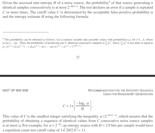
NIST SP 800-90B section 4.4 specifies some health tests. The NIST spec seems to be fairly well regarded, so I’ll use this as a starting point for our tests. The tests come with the caveat that they only detect catastrophic failures in the TRNGs; they are no substitute for a very detailed, long-run statistical analysis of the TRNG outputs at the design phase (which we have already done). NIST recommends two tests: a repetition count test, and an adaptive proportion test.
This is the repetition count test:
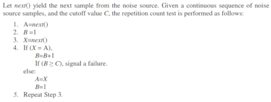
With the following criteria for failure:
And this is the adaptive proportion test:
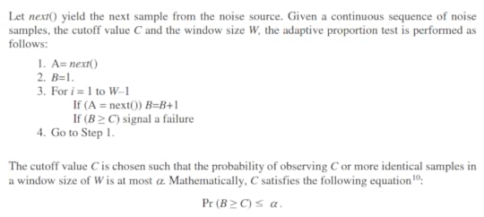
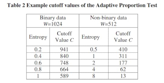
With the following example cutoff values:
OK, so now we know the tests. What do these even mean in the context of our TRNGs?
Ring Oscillator ImplementationsOur Ring Oscillator architecture consists of 33 independent ring
oscillators that operate in two phases. In the first phase, the rings oscillate independently of each other to collect phase noise; the state of each ring is XOR’d into a state bit through snapshots taken at regular intervals. In a second phase, they are merged into a single large ring oscillator, where they then have to reach a consensus. A single bit is taken from the consensus oscillator, and progressively shifted into the state of the ring oscillator.
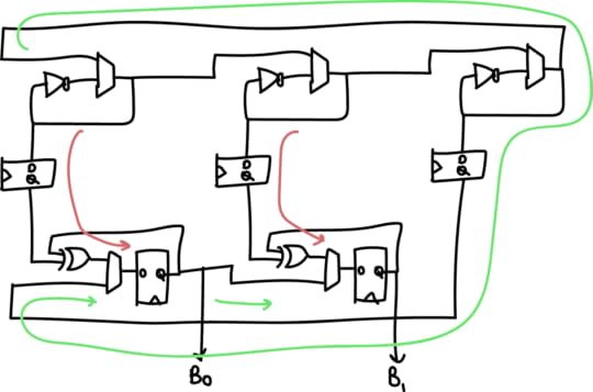
Above is a simplified “two bit” version of the generator, where instead of 33 oscillators we have 3, and instead of 32 bits of entropy we get 2. The red arrow is the flow of entropy in the first phase, and the green arrow is the flow of entropy in the second phase. The two phases are repeated N+1 bit times (33 times in the full implementation, 3 times in the simplified diagram above).
We can see from the diagram that entropy comes from the following
sources:
The global phase consensus and cross-element mixing is quite important because ring oscillators have a tendency to couple and phase-lock due to crosstalk side-channels on both signal and power. In this architecture, each ring’s local noise conditions, including its crosstalk, is applied across each of the 32 output bits; and each ring’s oscillation is “reset” with an arbitrary starting value between each cross-element phase.
A higher rate of aggregate entropy is achieved by running four instances of the core described above in parallel, and XOR’ing their result together. In addition, the actual delay/dwell parameters are dynamically adjusted at run-time by picking some of the generated entropy and adding it to the base dwell/delay parameters.
Thus, when looking at this architecture and comparing it against the NIST spec, the question is, how do we apply the Repetition Count test and the Adaptive Proportion tests? The Repetition Count test is probably not sensitive enough to apply on the 32-bit aggregate output. It’s probably best to apply the Repetition Count and Adaptive Proportion test a bit upstream of the final generated number, at the sampled output of the ring oscillators, just to confirm that no constituent ring oscillator is “stuck” for any reason. However, the amount of logic resources consumed by adding this must be considered, since we have (33 * 4) = 132 separate oscillators to consider. Thus, for practical reasons, it’s only feasible to instrument one output from each of the four cores that is indicative of the health of the entire bank of oscillators.
Picking the right spot to instrument is tricky. The “large” ring oscillator is actually low-quality entropy, because it has a period of about 30MHz but is oversampled at 100MHz. Thus the majority of the entropy is contributed from the repeated undersampling of the “small” rings. The final sampling point chosen is the output of the sampling register after it’s “soaked up” enough entropy from the combination of a small ring and a large ring to result in a useful measurement.
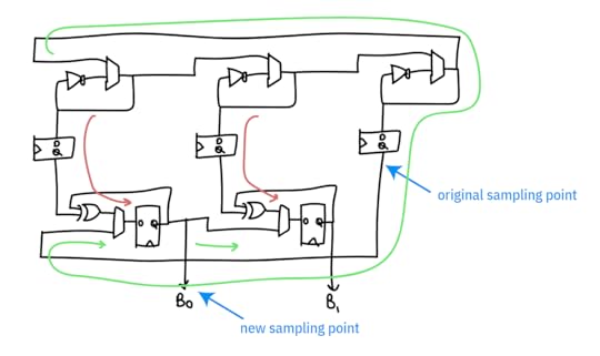
Originally, I had tried looking at the “large” oscillator only to try to find something more “raw”, under the hypothesis that we would be more likely to catch problems in the system at a less refined stage; the problem is that it was so “raw” that all we caught was problems. However, we do use this tap as a “true negative” test, to ensure that the health tests are capable of flagging an entropy source that is less than perfect.
I’m also going to introduce an extra test that’s inspired by the Runs Test in the STS suite, that I call “MiniRuns”. This test records the frequency of continuous runs of bits: 0/1, 00/11, 000/111, 0000/1111, etc. This test will offer more insight into the dominant projected failure mode of the ring oscillator, namely, it oscillating as a perfectly synchronized square wave — a condition that neither of the recommended NIST tests are capable of capturing. However, if the oscillator becomes too deterministic, we should see a shift in the distribution of run lengths out of the MiniRuns test.
Avalanche Generator ImplementationThe avalanche generator consists of two avalanche diodes biased from a shared power supply, sampled by a pair of op-amps with a slight bit of gain; see our page on its theory of
operation for details on the physics and electronic design. Here, we focus on its system integration. The outputs of each of the op-amps are sampled with a 12-bit ADC at a rate of ~1MSPS, and XOR’d together. As this sampling rate is close to the effective noise bandwidth of the diodes, we reduce the sampling rate by repeatedly shifting-by-5 and XOR’ing the results a number of times that can be set by software, nominally, 32 times into a 32-bit holding register, which forms the final entropy output. This 32x oversampling reduces the rate of the system to 31.25kHz.
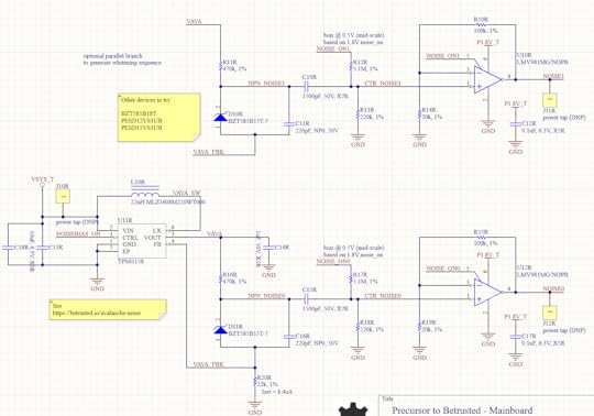
Thus in this scheme, entropy comes from the following sources:
The avalanche properties of two individual diodes. These are considered to be high-quality properties derived from the amplification of true thermal noise.The sampling interval of the ADC versus the avalanche waveformNoise inherent in the ADC itselfNote that the two diodes do share a bias supply, so there is an opportunity for some cross-correlation from supply noise, but we have not seen this in practice.Because we are oversampling the avalanche waveform and folding it onto itself, what we are typically measuring is the projected slope of the avalanche waveform plus the noise of the ADC. Significantly, the SNR of the Xilinx 7-series “12-bit” ADC integrated into our FPGA is 60dB. This means we actually have only 10 “good” bits, implying that the bottom two bits are typically too noisy to be used for signal measurements. The XADC primitive compensates for this noise by offering automatic averaging over 16 samples; we turn this off when sampling the avalanche noise generators, because we actually *want* this noise, but turn it on for all the other duties of the XADC.
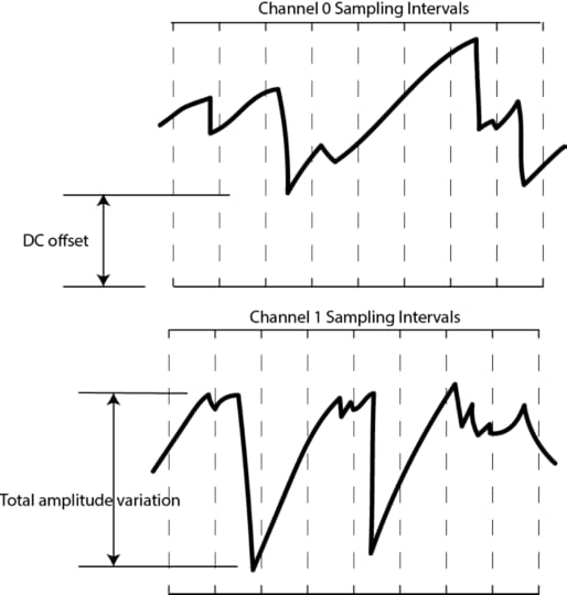
It’s also important to consider the nature of sampling this analog
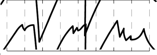
waveform with an ADC. The actual waveform itself can have a DC offset, or some total amplitude variation, so naturally the LSBs will be dense in entropy, while the MSBs may be virtually constant. By focusing on the bottom 5 bits out of 12 with the 5-bit sliding window, we are effectively ignoring the top 7 bits. What does this do to the effective waveform? It’s a bit easier to show graphically:
Below is a waveform at full resolution.
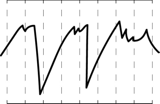
If we were to only consider 11 bits out of the 12, we effectively take half the graph and “wrap it over itself”, as shown below:
Down to 10 bits, it looks like this:
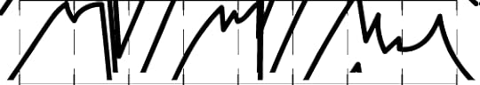
And down to 9 bits, like this:

And so forth. By the time we are down to just considering 5 bits, we’ve now taken the effective DC offset and amplitude variations and turned them into just another random variable that helps add to the entropy pool. Now take two of these, XOR them together, and add in the effective noise of the ADC itself, and you’ve arrived at the starting point for the ADC entropy pool.
In terms of on-line entropy tests, it probably makes the most sense to apply the Repetition Count test and the Adaptive Proportion tests to the bottom 5 bits of the raw ADC feed from each avalanche diode (as opposed to the full 12-bit output of the ADC). We don’t expect to hit “perfect entropy” with the raw ADC feed, but these tests should be able to at least isolate situations where e.g. the bias voltage goes too low and the avalanche effect ceases to work.
In addition to these tests, it’s probably good to have an “absolute
excursion” test, where the min/max of the raw avalanche waveforms are recorded over a time window, to detect a diode that is flat-lining due to aging effects, or a bias voltage source that is otherwise malfunctioning. This test is not suitable for catching if an attacker is maliciously injecting a deterministic waveform on top of the avalanche diodes, but is well-suited as a basic health check of the TRNG’s core mechanisms under nominal environmental conditions.
After installing the tooling necessary to build a Precursor/Betrusted SoC, I started writing the code.
Here’s the general method I use to develop code:
Think about what I’m trying to do. See the first section of thisarticle.Write the smaller submodules.Wrap the smaller modules into a simulation framework that shakes
most of the skeletons out of the closet.Repeat 1-3, working your way up the chain until you arrive at your full solution.Write drivers for your new featureSlot your feature into the actual hardwareTest in real hardwareContinuously integrate, if possible, either by re-running your sim against every repo change or better yet recompiling and re-running your test on actual hardware.
The key to this loop is the simulation. The better your simulation, the better your outcome. By “better simulation”, I mean, the less
assumptions and approximations made in the test bench. For example, one could simulate a module by hooking it up to a hand-rolled set of Verilog vectors that exercises a couple read and write cycles and verifies nothing explodes; or, one could simulate a module by hooking it up to a fully simulated CPU, complete with power-on reset and multiple clock phases, and using a Rust-based framework to exercise the same reads and writes. The two test benches ostensibly achieve the same outcome, but the latter checks much more of the hairy corner cases.
For Betrusted/Precursor, we developed a comprehensive simulation framework that achieves the latter scenario as much as possible. We simulate a full, gate-level Vex CPU, running a Rust-built BIOS, employing as many of the Xilinx-provided hardware models as we can for things like the PLL and global power-on reset.
DemoThis is the point in the cooking show at which we put the turkey into an oven, say something to the effect of “…and in about five hours, your bird should be done…” yet somehow magically pull out a finished turkey for carving and presentation by the time we finish the sentence.
So: after a bunch more driver-writing and breaking out signals to gain visibility into the various metrics and failure modes, we can see the on-line health tests in action.
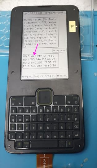
Above is an example of the trng test data output on Precursor, set where `RO 0` is connected to the “large” oscillator that runs too slowly (serving as a “true negative” test), and the others are connected to the final output tap for the test (serving as a “true positive”). In the output, you can see the four ring oscillators (numbered 0-3) with the frequency of each of five run lengths printed out. `RO 0` has a significant depression in the count for the run-length 1 bin, compared to the other oscillators (440 vs 515, 540, and 508).
One final detail is implementing an automated decision mechanism for the MiniRuns test. Since the MiniRuns test wasn’t from the NIST suite, I couldn’t simply read a manual to derive a threshold. Instead, I had to consult with my perlfriend, who also happens to be an expert at statistics, to help me understand what I was doing and derive a model that could help me set limits. Originally, she suggested a chi-square test. This would be great, but the math for it would be too complicated for an automated quick power-on test. So, we downgraded the test to simple max/min thresholds on the counts for each “bin” of runs. I used a similar criteria to that suggested in the NIST test, that is, 𝛂 = 2^-20, to set the thresholds, and baked that into the hardware code. Here’s a link to the original spreadsheet that she used to compute both the chi-square and the final, simpler min/max tests. One future upgrade could be to implement some recurring process in Xous that collects updated results from the MiniRuns test and does the more sophisticated chi-square tests on it; but that’s definitely a “one for the road” feature.
Closing ThoughtsThe upshot is that we now have all the mandatory NIST tests plus one each “tailored” tests for each type of TRNG. Adding the MiniRuns automated criteria increased utilization to 56.5% — raising the total space used by the tests from about 2% of the FPGA to a bit over 4%. The MiniRuns test is expensive because it is currently configured to check for runs ranging from length 1 to 5 over 4 banks of ring oscillators — so that’s 5 * 4 * (registers/run ~30?) = ~600 registers just for the core logic, not counting the status readout or config inputs.
Later on, if I start running out of space, cutting back on some of the instrumentation or the depth of the runs measured might be a reasonable thing to do. I would suggest disposing of some of the less effective NIST tests entirely in favor of the home-grown tests, but in the end I may have to kick out the more effective supplemental tests. The reality is that it’s much easier to defend keeping inferior-but-spec-compliant tests in the system, rather than opting for superior tests at the expense of the specification tests.
That’s it for part 1. If you’re super-eager to read more, you can read the full wiki entry on data conditioning for the TRNG at the Precursor/Betrusted documentation wiki. Or, you can just wait until I get around to chopping the page down to size and repackaging it into a more bite-side blog entry.
Upgrading Precursor’s TRNG
It was pointed out that we’re missing a step-by-step guide on how to go from an idea, to hardware, to a fully implemented feature in Xous for Precursor. So, here it is.
Because Precursor uses an FPGA for its SoC, we can add new features to the hardware “on the fly”. In this case, we’re going to add some improvements to our basic managed TRNG block. To review, the existing TRNG consists of an avalanche noise source and a ring oscillator noise source as hardware-based sources of “true” entropy. Two generators are used for the following reasons:
An external discrete generator is easy to check (just put an oscilloscope on the avalanche noise source), but harder to protect against physical access attacksAn integrated, on-chip generator is harder to hack (more robust against a pair of tweezers executing a short-to-ground attack, or RF interference attacks), but harder to check (is the data from the TRNG, or merely a decoy CSPRNG implant?)All hardware mechanisms are fallible; having two sources improves robustness against transient drop-outs or aging failuresWe’ve already done extensive, months-long characterization of both of the TRNG sources and found them to produce passable raw entropy. However, the system is still missing two features that are generally considered to be best practice:
Independent, on-line health monitors of the raw TRNG outputs. It’s important that the health monitoring happens before any conditioning or mixing of the raw data happens, and significantly, there is no one-size-fits-all health monitor for a TRNG: it’s advised (NIST SP 800-90B sec 4.4) to have tests that are tailored to the noise source.Conditioning of the raw data. Despite best efforts to make TRNGs unbiased and flawless, they are really hard to get right. Furthermore, they are only capable of producing high-quality entropy at a limited data rate. Thus, most practical systems take a TRNG output and run it through a cryptographic stream cipher to generate a final datastream; this simultaneously protects against minor flaws in the TRNG while improving the availability of random numbers.The following lengthy posts walk step-by-step through the thought process, implementation and debugging process of adding these features. Few people would even notice these features, and if everything is doing its job right (that is, the TRNG’s raw data is working correctly) is indistinguishable from the state before all this effort. However, we take TRNGs seriously here; so much rides on the quality of these random numbers that it’s probably worth the effort to harden them against failures, be they unintentional, malicious, or just design bugs.
I have to be honest, I spent a lot of time to check a box that few people care about, but I’ve come to realize that’s mainly what writing OS code and firmware is about. You can get more fame and dopamine from creating a cool UI theme with an afternoon of work. It’s also really hard to explain to everyday people what you’re doing exactly with all this time and effort; but without the underlying frameworks that make things durable and reliable, we all might as well be drawing chalk pictures on the side walk.
Without further ado, here are the two guides for adding features, there’s some repetition between the posts so they can be read independently.
On-line health monitorsRaw data conditioningI’ll also take highlights from these wiki articles and repost them to the blog here, creating a “TL;DR” version that is also neatly delivered to the inboxes of my blog’s email subscribers.
Winner, Name that Ware April 2021
Somehow, this didn’t get posted when I hit the post button, and I never noticed! I just saw that the new ware was up and assumed this went through as well. Sorry about that!
The boards from April 2021 were from a Bruker NMS120 benchtop NMR analyzer — according to the contributor of the ware, they “generate RF output to the power amp, digitize (downconverted) RF input, and generate some extra control signals”.
I’m always pleased when I manage to blur a logo just enough that you can’t Google image search it, yet it’s somehow recognizable to humans. Someday machines will beat us at this game but, for now, maybe there’s still a place for human experience vs merely large training sets thrown into a DNN!
Picking a winner is much harder this month. Because I don’t know the much larger system-level context from which these come, I can’t know if Willmore’s final guess is correct or not (but perhaps Don Straney can weigh in). Absent that bit of information, I found Zebonaut’s insights about the cultural biases of German PCB design to be really insightful. I can usually pick out a Japanese-made board based on stylistic decisions, but until now I hadn’t heard such a nice summary of some of the biases and preferences of German PCB designers. So, I’ll give the prize to Zebonaut for that bit of insight, along with a generally correct guess on the make and genre of the ware, which I’m unable to resolve further due to my own ignorance. Congrats, email me for your prize!
May 31, 2021
Name that Ware May 2021
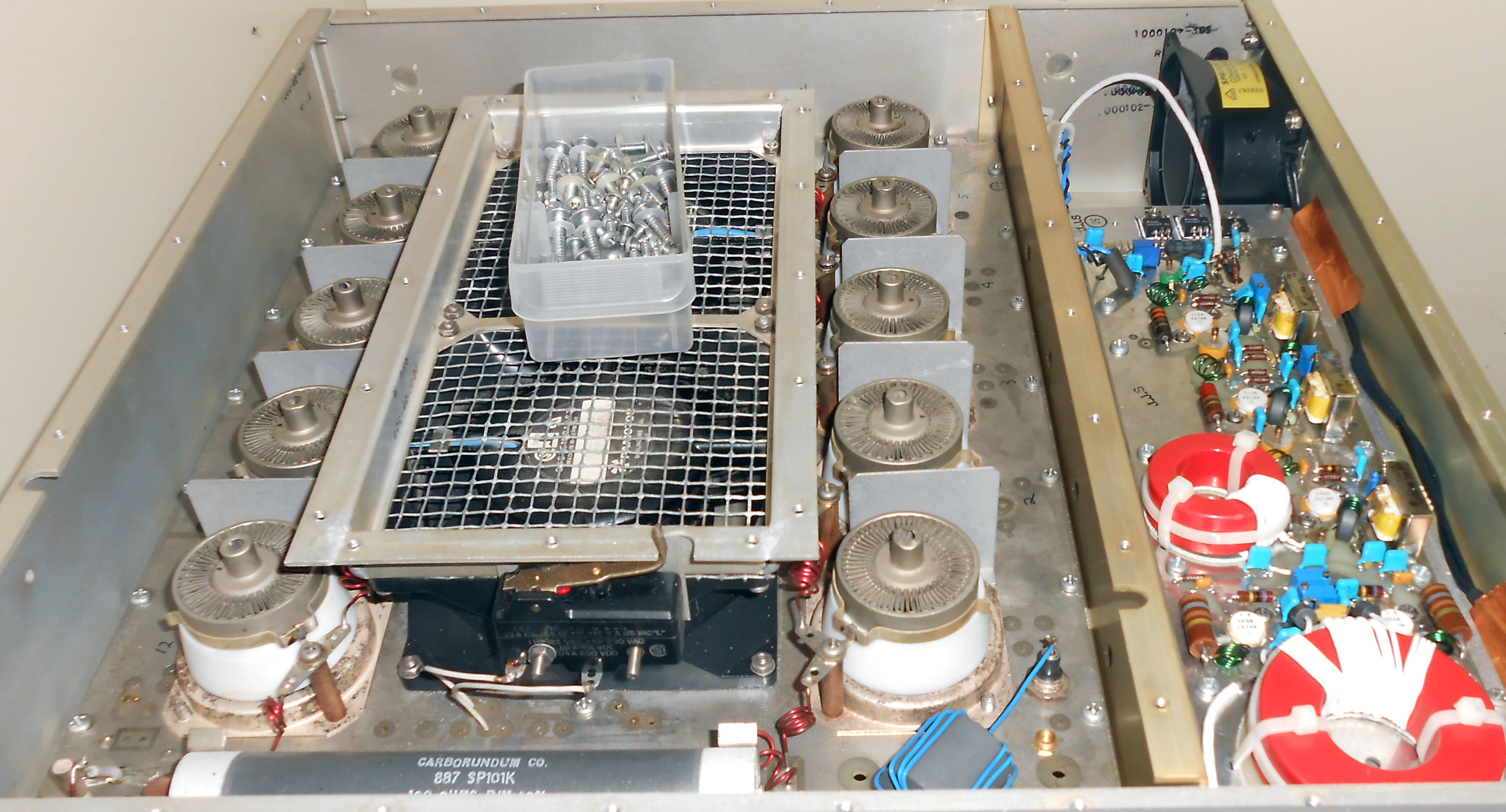
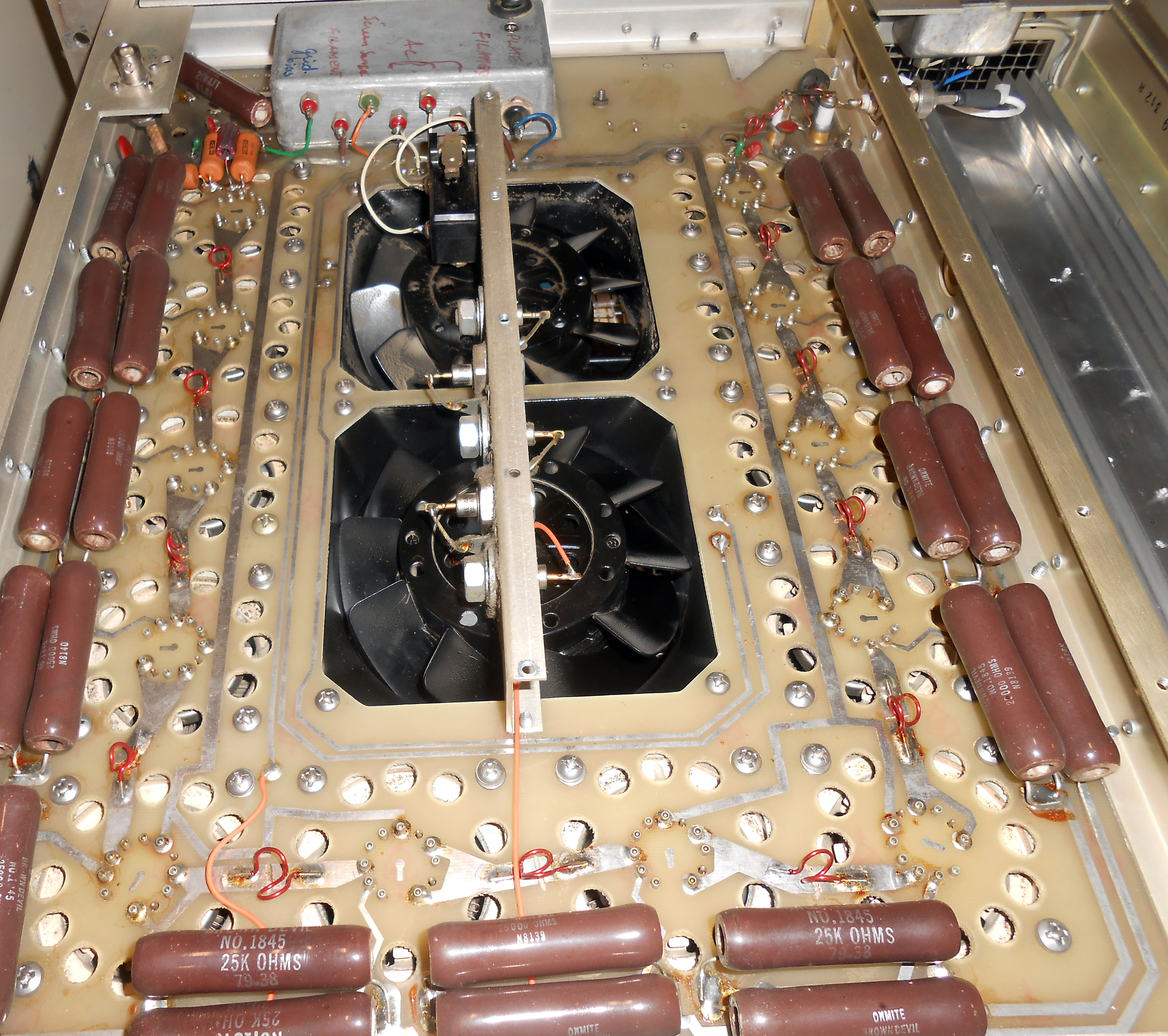
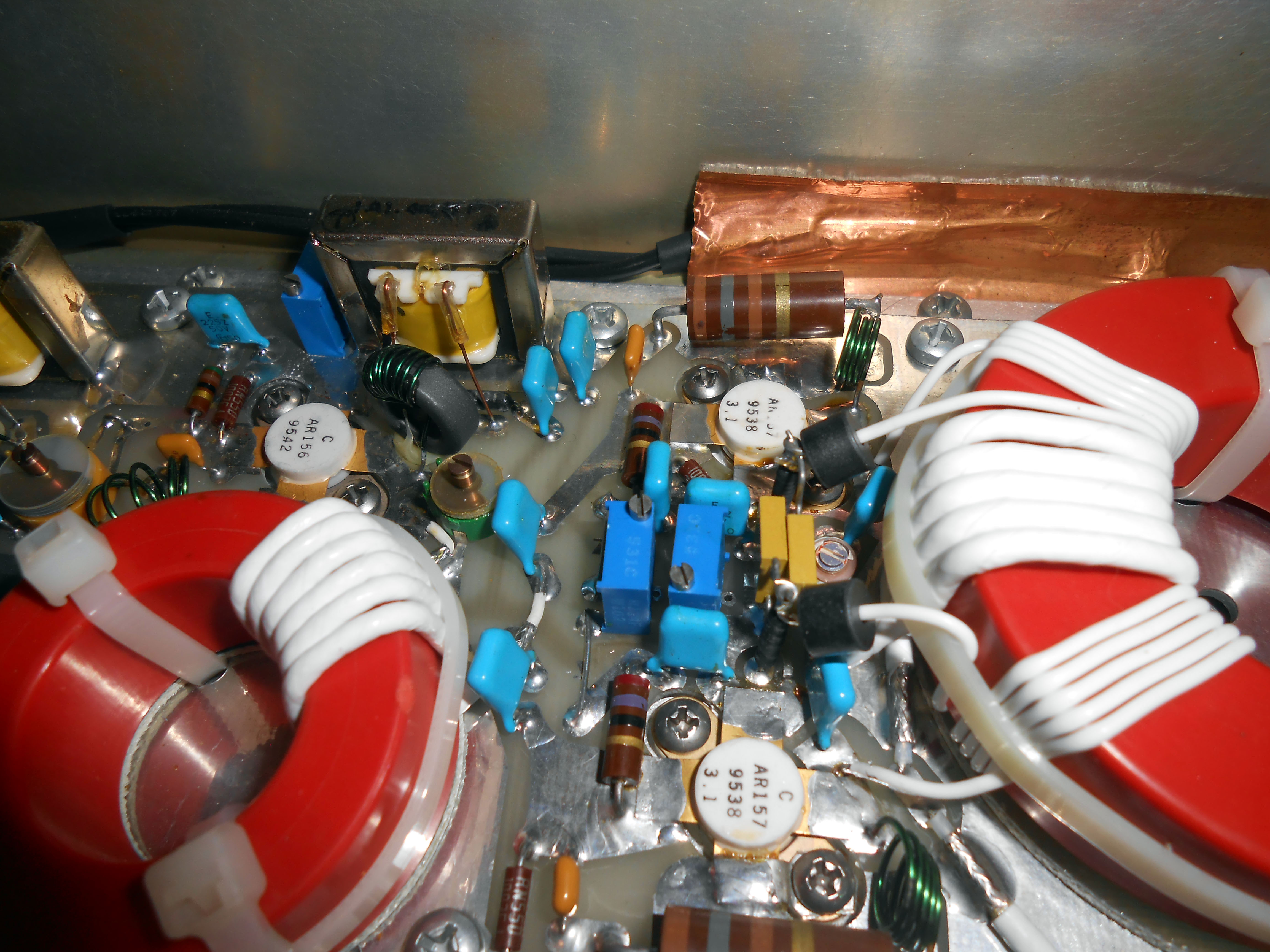
The Ware for May 2021 is shown below:
This ware might be a bit too bespoke for a fair shake at guessing what it is, but based on the previous months’ performances, maybe we’re due for something on the more difficult side. I did rather like the nice patch boards partially visible in the bottom of the photos. These are, once again, contributions from Don Straney.
April 30, 2021
Name that Ware April 2021
The Ware for April 2021 is shown below.
Both boards are from the same machine. I really admire the construction quality of these boards! Thanks again to Don Straney for contributing these fascinating wares.
Winner, Name that Ware March 2021
The Ware for March 2021 is a fire control system (not fire as in “artillery fire”, but fire as in “your building is on fire”) controller, a Honeywell HS-NCM-SF. It’s the sort of board that lives in those red boxes hanging near the entrance of big buildings with fancy fire alarm systems.
A quick Internet search shows these things go for around US$2k retail. This pricing is commensurate with a “made in USA” process, B2B volumes, and its choice of top-shelf parts, even though its specs are fairly modest if not strange. When I first saw this, I scratched my head at the use of fiber optic comms, matched with a CPU that was clearly not capable of handling fiber optic data rates. Once I learned its purpose, it made a bit more sense. At least, I’m presuming the fiber optics are chosen either because there is a reliability advantage in the context of fire-resistance of the cabling, or perhaps the fiber optics are advantageous because there is no risk of sparking wires in the case that one end of the line is engulfed in fire and presumably melts into a glob of metal that includes the power mains.
Again, Willmore nailed it. Congrats, email me for your prize!
Andrew Huang's Blog

- Andrew Huang's profile
- 32 followers

