
Russell Phillips's Blog, page 4
March 8, 2021
International Women’s Day: Berthe Mayer, MBE

Today is International Women’s Day. This seems like an appropriate time to write about Berthe Mayer, MBE.
In October 1941, Berthe and her husband Percy Mayer lived on the island of Madagascar. The island was under the control of Vichy France, and the couple were SOE (Special Operations Executive) operatives. Berthe, designated DZ/60, operated the radio for her husband. While he was away in South Africa, she gathered and transmitted intelligence about Vichy merchant ships. Acting on this intelligence, the Royal Navy intercepted and captured five ships, totalling 40,000 tons. For this, she received the personal thanks of Admiral Godfrey, the director of Naval Intelligence. Although the Allies didn’t know it, her intelligence led the Germans to distrust Vichy security. As a result, the Vichy French couldn’t send reinforcements to Madagascar when the Allies invaded.
The Vichy French authorities arrested Percy Mayer shortly after the British invasion in May 1942. British forces arrived just in time to save him from execution. Berthe was in the Vichy-controlled capital, Tananarive. During the attack on Diego Suarez, she sent a warning about Vichy forces planning to advance on the British in the north.
Later in May, the Vichy authorities realised that radio transmitters were in use, and offered large rewards to anyone that helped find them. They searched Berthe’s house and placed her under close surveillance. The authorities used radio direction finding equipment, and they cut the electricity to certain parts of the city. Both SOE and her husband warned Berthe to stop transmitting. She ignored them, sending nightly reports of political and military intelligence, including details of defences and troop movements. Reports stated that this intelligence was of “invaluable assistance to the attacking forces.”
RecognitionMadagascar finally surrendered in November 1942. High-ranking officials knew how much Berthe and Percy had hlep. They worked to ensure that they got the recognition they deserved. They recommended Berthe for an MBE and Percy for an OBE. Some officials believed Berthe was French, which caused some delays.
In April 1943, Field Marshal Jan Smuts, the South African Prime Minister, chased the matter up. He stated that both Percy and Berthe deserved “very great personal recognition” and that it had already been “far too long delayed.”
SOE finally received the OBE and MBE insignia later in April, for them to give to Percy and Berthe Mayer. Lord Selborne, the Minister for Economic Warfare, didn’t think this was good enough. He pointed out that their work was worthy of higher honours, which he would have requested had they been eligible. Since that wasn’t possible, he requested that King George himself present the OBE to Percy Mayer, and this happened in June. Percy was still an active SOE agent, so it was a private ceremony. The King also gave Percy the MBE insignia for Berthe at the ceremony.
Berthe finally received formal recognition for her brave work in November 1943, about a year after the surrender of Madagascar to which she had contributed so much. Lord Harlech, the High Commissioner to South Africa, presented her with the MBE. An SOE report described it as an “impressive little ceremony”.
For more about the battle for Madagascar, see my upcoming book, A Strange Campaign.


January 12, 2021
The Soviet BREM-1 Armoured Recovery Vehicle
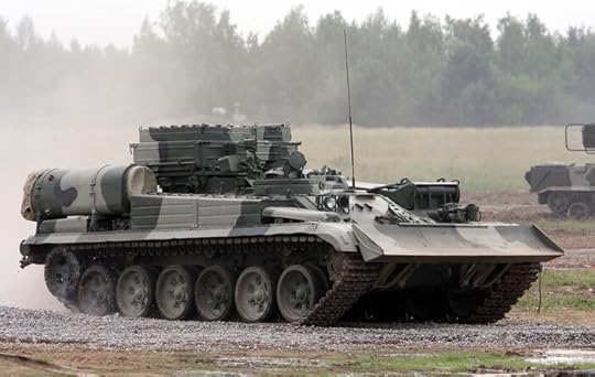
In contrast to the German army during the Second World War, the Soviet army did not have specialised recovery vehicles or tactics for using them. They started to experiment with their use at the end of the war, initially using locally-modified versions of existing vehicles, often turretless T-34s. After the war, they began producing dedicated vehicles with specialised equipment. One of these was the BREM-1, based on the chassis of the T-72 main battle tank.
BREM-1Introduced in 1984, the BREM-1 had a crew of three (driver,commander, and mechanic), all of whom were provided with day andnight-vision equipment. It had a top road speed of 60km/hour, a roadrange of 700km, and an off-road range of 500km. Towing another tanksignificantly reduced the range, to just 220km on roads. Like themain battle tank on whose chassis it was based, it had long-rangefuel drums at the rear of the vehicle, which could be jettisoned ifneeded. An unditching beam was mounted underneath the external fueldrums. A large-diameter snorkel was carried on the rear right of thevehicle, which could be used for deep wading at depths of up to 5m.
A crane was fitted on the left side of the vehicle. This had alift capacity of 19 tonnes when extended up to 2m, or 3 tonnes at themaximum extension of 4.4m. The crane was powered hydraulically,normally using power from the vehicle’s main engine to run the pump.If the main engine was not running, the vehicle batteries could powerthe crane via an electrical pump. The crane was controlled from anelevated position, with a full set of controls. The crane turntablecould be locked, and the vehicle could travel over level ground witha load suspended from the crane. When in transit, the crane wasfolded down along the side of the vehicle and secured in place with aclamp.
A full set of electric welding equipment, including a workingposition, was carried in a hermetically-sealed panel over the lefttrack. Special tools were carried in portable containers on a loadplatform. This load platform was located at the centre of the roof,and was 1.7m long and 1.4m wide. It had removable side panels, andcould carry a load of up to 1.5 tonnes.
The BREM-1 had two winches, a plough, a bulldozer blade, andtowing equipment. The mechanical main winch had a 200m cable and abasic capacity of 25 tonnes. Snatch blocks could be used to increasethis capacity to 100 tonnes. The winch was normally used at thefront, with the bulldozer blade to anchor the vehicle, but it couldalso be used to the rear for self-recovery.
The bulldozer blade was 3.1m wide and hydraulically driven, usingcontrols at the driver’s station. A BREM-1 could use this blade tocreate an MBT firing position in 12 to 20 minutes, depending on thestate of the soil.
For towing, the vehicle had a pair of 1.68m towing rods, with internal shock absorbers, and a pair of 5.5m towlines. Loads of up to 50 tonnes could be towed for prolonged periods, at the cost of greatly increased fuel consumption.
Other equipment included a 30-tonne capacity hydraulic jack,R-123U radio, tank telephone system, navigation system, and NBCprotection. Armour protection was the same as the T-72 MBT, althoughthe only armament was a 12.7mm NSVT machine gun with 840 rounds ofammunition. Four smoke-grenade dischargers were sometimes fitted, andall vehicles could create a smokescreen by injecting diesel fuel intothe exhaust manifold.
Specifications: BREM-1Crew: 3
Weight: 41 tonnes
Length: 7.98m
Width: 3.46m
Height: 2.43m
Ground clearance: 0.46m
Maximum road speed: 60km/hour
Maximum road range: 700km
Gradient: 60%
Vertical obstacle: 0.85m
Armament: 1x 12.7mm NSVT MG (840 rounds)
Image credit: Vitaly V. Kuzmin (CC BY-SA 4.0)
November 13, 2020
The Tetrarch was not designed as an airborne tank
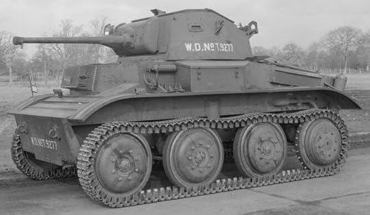
The British A17 Tetrarch light tank is best known for its role in Operation Overlord, where they landed in Hamilcar gliders in support of the airborne troops. It’s often said that the Tetrarch was designed from the outset as an airborne tank, but that’s a myth.
Vickers designed the Tetrarch, which followed on from their Light Tanks, Marks I to VI. The Tetrarch was the Light Tank, Mark VII and was designed for the same roles as the earlier marks. The British army accepted it for service and production was due to begin in 1940. Few were built, as the War Office concentrated on cruiser tanks and infantry tanks after the Battle of France.
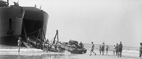
Britain sent twenty Tetrarch tanks to the USSR under lend-lease, where they served in the light tank role. Six others went to Madagascar, forming half of B Special Service Squadron of the Royal Armoured Corps. They took part in the initial amphibious invasion and capture of Diego Suarez, operating as standard light tanks. They were later re-embarked for Operation Stream to take Majunga, but in the event they were not needed.
The Tetrarch’s use as an airborne tank came later, and trials with Hamilcar gliders only began in 1944. These airborne tanks were fitted with Littlejohn adaptors or had their 2-pounder guns replaced with 3″ howitzers for use as infantry support tanks.
November 11, 2020
Remembrance Day 2020
Today is Remembrance Day in the UK. I have a poppy, and I shall observe the two minute silence at 11:00.
For me, this is a day to remember everyone that has been harmed by war. Whatever their nationality, and whether they were civilian or military. That’s a lot of people, and so each year I focus on one particular group.
This year, my focus will be on those that fought in campaigns that are not well remembered. My next book is about the battle for Madagascar in WWII. It’s mostly forgotten now, but men and women fought and died on the island. They deserve to be remembered just as much as those that fought in other, better-known campaigns.
Like many others, until relatively recently I knew very little of the campaign, and there are probably others that I’m still unaware of. At 11:00 today I shall think of those that fought and died in battles that most people no longer remember.
September 7, 2020
A Strange Campaign available for pre-order

On 5th May next year my next book, A Strange Campaign: The Battle for Madagascar, will be published. This coincides with the anniversary of Operation Ironclad, which marked the start of the campaign.
It will be available in hardback, paperback, ebook, large print, and (hopefully) audio book. All formats should be available on 5th May, but the hardback, paperback, and ebook are available for pre-order now.
Hardback
Paperback
Ebook
Kindle : Kobo : Apple iBooks : Nook
Book Description
Madagascar provided the stunning backdrop for one of the strangest conflicts of the Second World War — when Britain went head to head against one of its closest allies.
When British forces landed on the island in 1942, the enemy they faced wasn’t German, Japanese or even Italian, this time the opposing forces were French.
Concerned that Japan might use Madagascar as a strategic base to disrupt the supply line to India, Britain was keen to take control of the island. However, the Vichy forces were keen to defend the French colony and prevent it becoming part of the British Empire.
A Strange Campaign: The Battle for Madagascar gives a detailed account of this fascinating but little-known period of military history. Even at the time, the conflict was a controversial one, pitting two colonial empires against each other.
However, it was also ground-breaking as it was the first time Allied forces had staged a major amphibious invasion. The lessons learned on the shores of Madagascar would prove to be invaluable two years later during the D-day landings in Normandy.
Military historian Russell Phillips examines the tactics used in the battle for Madagascar which included secret agents, dummy paratroopers and attempted bribery.
But just how did the British finally break down months of resistance by the French? And how did a tug-of-war over an island in the middle of the Indian ocean influence the rest of the Second World War?
July 7, 2020
My next book title is …?
My next book will be about the battle for Madagascar in WWII. It will cover the entire campaign, from the initial landings to the final Vichy surrender.
I’m still undecided about the title. Some possibilities are:
A Strange Campaign: The Battle for MadagascarA Faculty to Dare: The First Allied Invasion, Madagascar 1942Daring in Dark Days: The First Allied InvasionLet’s Risk Something: The Madagascar Campaign 1942
Which ones do you like or dislike, and why? Let me know in the comments.
May 5, 2020
The Iranian Embassy Siege: The Myth of the Wall

On 30th April 1980, terrorists stormed the Iranian Embassy in London and took twenty-six hostages. A six-day siege ensued, during which the embassy’s press attaché, Abbas Lavasani, was murdered. Forty years ago today, the SAS brought the siege to a dramatic end when they stormed the building and rescued the hostages.
The Myth
On the last day of the siege Salim, the terrorist’s leader, noticed a bulge in the wall separating the Iranian and Ethiopian embassies. He pointed it out to PC Lock, one of the hostages. Both Salim and Lock believed that the police had tampered with the wall, weakening it for use as an entry point during an assault.
This claim appears to have first appeared in the book Siege! Princes Gate, London — The Great Embassy Rescue, published in 1980. The authors state that council workmen removed bricks from the wall to facilitate placement of pinhole cameras for surveillance. Other books and articles claim that bricks were removed, leaving just a thin layer of plaster, so that the SAS could burst through the walls and into the embassy. The only evidence for these claims appears to be PC Lock’s testimony. Remember that after six days as a hostage, he was tired and emotionally overwrought. There may have been a bulge in the plaster, but not because bricks had been removed.
The Evidence (or lack thereof)
Two days after the assault, the Metropolitan Police Headquarters Surveyor submitted a report detailing damage done to the Ethiopian embassy during the siege. The report notes that there was no police occupation of the embassy during the siege. It doesn’t mention bricks missing from walls, or holes in the wall adjoining the Iranian embassy. An official from the Ethiopian embassy was present during the survey. The Ethiopians were pressuring the UK government for compensation, so had an interest in ensuring all damage was catalogued.
According to builders I consulted, it would be difficult to remove the bricks from one side of a wall whilst keeping the plaster on the far side. It might be possible, if the plaster had separated from the bricks on the Iranian side, but even then it would not be easy. Having no access to the Iranian side of the wall, the police wouldn’t have been able to determine whether or not the plaster had separated. If it hadn’t, large holes would have appeared in the wall when the bricks were removed, with disastrous effects.
The UK Home Office produced an internal history of the siege. It doesn’t mention bricks being removed from adjoining walls for any purpose.
Some accounts claim that enough bricks were removed to allow entry through the wall. If so, why wasn’t it used? In hostage-rescue operations, speed and surprise are critical to success. De la Billière said of the plan, “The essence of it was speed and surprise”. Going through the wall would have provided fast entry into the heart of the building, close to where the hostages were held, without the potential problem of barricaded doors.
SAS veterans of the siege have published several first-hand accounts. None of them mention an attempt to remove bricks from walls to gain an additional entry point. Nor is it mentioned in General (then Brigadier) Sir Peter de la Billière’s memoirs.
Finally, at least one source claims that army engineers did the work, not council workmen. Although this is a small discrepancy, it adds to the general weight of evidence.
Conclusion
It is notoriously difficult to prove a negative. But the above evidence strongly suggests that claims of bricks being removed in the adjoining wall is just an urban myth.
There is more about the siege and the SAS assault in my book Operation Nimrod: The Iranian Embassy Siege.
March 17, 2020
Project Prodigal and the British Army’s Flying Cars

On a visit to the National Archives, I ordered document AVIA 65/1540, “Project PRODIGAL: army vehicle with limited airborne capability”. I was expecting it to be about FV4401 Contentious, a possible design for an air-portable tank destroyer. In fact, it was about something quite different — flying cars! This article is based on that document.
Introduction
In the late 1950s and early
1960s, the British army’s Fighting Vehicles Research and Development
Establishment (FVRDE) investigated possible future fighting vehicles.
A number of investigations were launched, all under the name “Project
Prodigal”. One such investigation was FVRDE specification 9258, for
a scout car with a limited ability to fly. The specification was
vague regarding the flight capability, which could be limited to
jumping over obstacles, or extend to steady flight for several miles.
The vehicle was envisioned
primarily as a ground vehicle with good cross-country performance.
Flight was only to be used when it was unable to continue over
ground, since it was felt that the enemy would be less likely to
detect a ground vehicle. The requirement was for a vehicle no larger
than 16 feet long and eight feet wide. It was to have a crew of two,
and no armament was specified, though it was to carry radios and have
sufficient fuel to travel at least 200 miles on the ground. Armour
protection was not required, since it was understood that weight
would be at a premium.
Nine potential solutions
were submitted, by seven companies. None of them appear to have got
as far as the prototype stage. Data sheets and small-scale models
were prepared, which offer a fascinating glimpse into what might have
been.
The flight capabilities of the submissions varied greatly, but all were able to perform the minimum requirement of jumping over an obstacle 30 feet wide and 10 feet high. Each vehicle was air-transportable by either a Blackburn Beverley or an Armstrong Whitworth AW.660 Argosy aircraft. Most provided sufficient cross-country performance, and were able to carry the required payload. The single exception was the Bristol Siddeley submission. This was a privately developed light vehicle with limited cross-country performance and half the required payload. The payload could be increased, but this would have come at a performance cost.
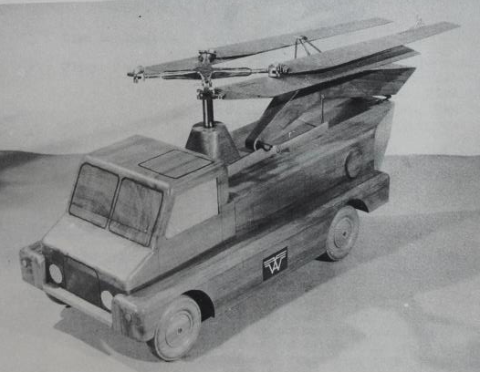
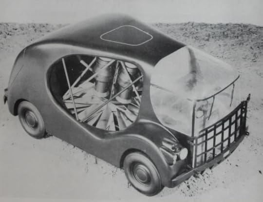
Westland No. 1
This vehicle consisted of a
four-wheel drive ground vehicle with helicopter rotors added. The
rotor assembly was taken from a Wasp helicopter, and the base vehicle
was similar to a Champ or Land Rover. When being driven on the
ground, the tail assembly folded over the rear of the vehicle,
reducing the length, and the main rotor was folded back.
Although the rotor assembly
was taken from a Wasp, the rotor control system was altered.
Stability was emphasised at the cost of manoeuvrability, to make the
vehicle easier to fly.
Preparation for flight involved unfolding the tail assembly and the rotors, and was expected to take between ninety seconds and two minutes.
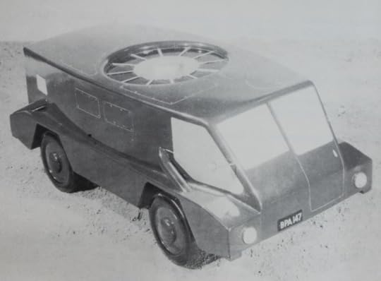
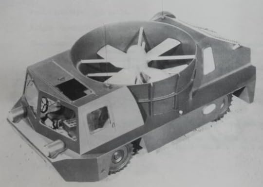
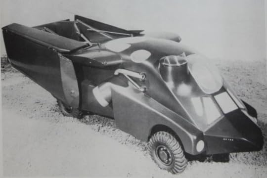 Handley Page vehicle with wings folded
Handley
Page 120B
This design was for a land
vehicle with folding wings and tail unit for flight. In the initial
(mark 1) design, two engines were required for flight. One powered a
large fan to provide lift, and a second provided lift or thrust via
swivelling side nozzles. The mark 2 design replaced these two engines
with a single BS 53/5 engine.
When jumping, the tail unit was extended, and the fan and nozzles provided the lift. If wing-borne flight was required, the tail unit would be extended, then the vehicle would take off vertically, using the fan and side nozzles, rotated to point down. Once airborne, the wings would be extended. Flight controls were similar to those of a conventional aircraft, although ailerons and rudder were inter-connected, to simplify flying.
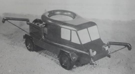
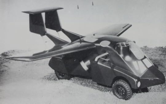 Handley Page vehicle with wings extended
The vehicle had a light
alloy frame, with light alloy or glass fibre panels. It was to be
lightly armoured, although armour thickness was not specified.
The vehicle could perform 45 jumps of 1,000 feet distance each, or fly just over 200 miles in one hour. With a long range fuel tank, flight distance could be extended to over 300 miles.
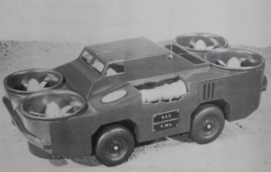
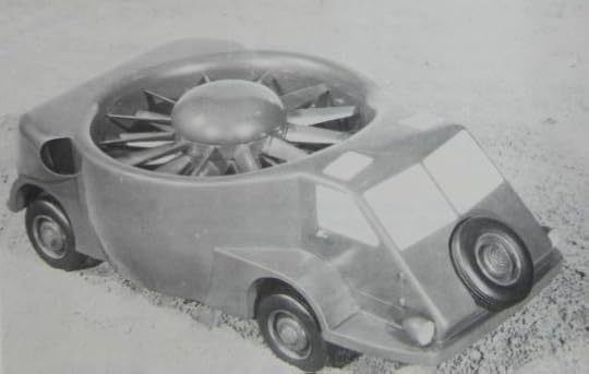
Vickers
Vickers worked with English
Electric on their proposal. This vehicle had four fans, one at each
corner of the vehicle, driven by a pair of DH Gnome gas turbine
engines. Forward propulsion was by tilting the vehicle. It could
perform 50 jumps of up to 1,000 feet, or fly for 30 minutes at a
speed of between 50 and 70mph.
Little consideration had been given to stability in flight, which the US had found to be an issue with four-fan vehicles. There were also concerns about visibility, since the driver was placed some distance from the front of the vehicle.
Bristol
Siddeley
This vehicle was a private
venture. It was relatively light, with poor cross-country performance
compared to the others. However, it had a good deal of redundancy
(any two of the three engines could provide sufficient power),
increasing reliability and safety. It was intended that longer
airborne range would compensate for poor cross-country performance.
Both fan and ground engines
were gas turbines, simplifying logistic issues by only requiring a
single type of fuel. The fan was tilted forward to provide forward
motion, and stability was provided by jets at the corners of the
vehicle. Extra movement in the steering column allowed the normal
driving controls to be used in flight.
The vehicle could reach altitudes of up to 10,000 feet, and could fly at 70-80mph for one hour. As designed, it could not carry the required payload. The full payload requirement could be achieved by sacrificing an engine or a quarter of the lift fuel. In the latter case, the flight time would be reduced to 45 minutes.
Boulton
Paul
Boulton Paul’s vehicle had a
light alloy structure with a large central fan. The ground
performance was expected to be comparable to that of the Ferret scout
car.
Forward propulsion was by
tilting the vehicle. Jets at the corners of the vehicle provided
stability and control, using the gyroscopic effect of the engine in a
flexible mounting to detect changes. In flight, it was steered using
the same controls as on the ground.
Airborne range was 43 jumps of 1,000 feet or a single long flight of 18 miles at 60-70mph. A second proposal was submitted, which used a different engine arrangement. This reduced the control power required, but also reduced airborne range slightly, to 40 flights of 1,000 feet.
Short
Brothers & Harland
This was another design with
a large central fan. Forward propulsion would be provided by tilting
the engine and the vehicle itself. Pipes extended from the corners of
the vehicle to provide stability, using a system similar to the one
used by the Short SC.1 experimental VTOL aircraft.
Control in flight used a small joystick, which was considered difficult for test pilots and almost certainly unsuitable for use by army drivers. On a more positive note, the vehicle was small and had good ground performance.
Handley
Page Type A
Two marks of this design
were developed, each using a large fan for lift. The mark 1 had
swivelling spherical nozzles, and three hydraulic jacks to provide
extra lift at take off. The mark 2 used side exits with nozzles to
provide lift or thrust. Pipes at the sides, front, and rear provided
control. The flight controls were separate from the driving controls.
Interestingly, ejector seats were included in the proposal.
The mark 1 could complete 48 jumps of 1,000 feet or steady flight of 44 miles at 127mph. The mark 2 increased this to 60 jumps, and with a tail unit fitted, could fly 80 miles at a speed of 200mph.
Folland
This vehicle emphasised
ground performance, with a jumping, rather than full-flight,
capability. It had large contra-rotating fans driven by compressed
air. The compressed air was supplied from storage bottles, which held
enough for two jumps of 30 feet at a height of 10 feet. Once the air
was used up, it could be recharged from the engine, taking at least
seven minutes. Recharging could be done while the vehicle was moving.
Pipes at the corners of the
vehicle provided stability, and the driver had little control during
flight, with pre-programmed vertical flight path. Forward propulsion
was provided by tilting the vehicle, or by momentum, taking off
whilst moving forward. It was believed that a jump of up to 750 feet
would be possible by performing a high-speed take off, and using both
air bottles to give 20 seconds of flight. The vehicle could swim
across rivers, and a hovercraft modification was also suggested.
Although the flight performance was less impressive than other submissions, it was relatively inexpensive, and offered near-instant flight provided the air bottles were charged.
Westland
No. 2
Unlike the other Westland
submission, this vehicle was not capable of full flight, only jumps
of up to 80 feet. It had a good cross-country performance, and a pair
of large contra-rotating fans, powered by the road engine. To jump,
the fan would be brought up to a high speed, then the blade pitch
would be changed to provide lift for up to five seconds. Blade pitch
was automatic, but the driver had a limited ability to control the
landing.
Forward propulsion was
provided by inclining the duct or tilting the vehicle. Control fans
or pressure jets at the corners would provide pitch and roll. Flight
controls were separate from the driving controls.
Since the fan was driven by
the road engine, the number of jumps was only limited by the fuel
available for ground travel. Fifty jumps could be performed with a
road range of 200 miles. For every extra jump, four miles of road
range were sacrificed.
Like the Folland design, the
vehicle could swim across rivers, and interestingly, it could perform
a jump from the water. One disadvantage of this design was noise. It
was likely to be audible at twice the distance of the other ducted
fan designs.
Conclusion
The idea never really
progressed, and none of the designs even reached the prototype stage.
Most designs were likely to be unarmoured, with the notable exception
of the Handley Page 120B. Armour protection on that model isn’t
specified, but weight considerations would have kept it very light,
probably only proof against small arms and shrapnel at best. Armament
was not specified for any of the designs, and it seems likely that
they would have been unarmed.
February 6, 2020
The Joy of Hex — Making a Hex Mat for Wargaming

A little while ago, I decided to try miniature wargaming on a hex grid. There are plenty of companies that will supply wargaming mats printed with hexagons or squares. I already had two plain green mats that I’d bought cheaply, and didn’t really want the expense of a commercially-printed mat, so I set out to turn one of them into a hex mat.
Making a Hex Mat
First, you need a paper template. I used the graph paper PDF generator at http://incompetech.com/graphpaper/hexagonal/ to create a PDF file with hexes 2″ across, then printed it onto ordinary paper.
Keep the margins as small as possible, so that you get more hexes on the paper. I didn’t do this, and regretted it, so learn from my mistakes! More hexes on the template make it quicker and easier to draw the hexes onto the mat, and the end result will be better quality. Cut the hexes out, and use a sharp pencil or similar to make a hole at each corner. This is your template.
Place the template in one corner of your mat and use a Sharpie or similar to mark the position of each hole. I used a black fine-point Sharpie, but of course the thickness and/or colour can be altered to make the hex lines more or less obvious, according to your preference.
 Marking the hexes onto the mat
Move the template away, and use a ruler to draw lines between the dots to make the hexes. Line up your template against the newly-drawn hexes and repeat. If your dots are visible enough, it may be better to mark all the dots, then add the lines. I didn’t do that, but it would allow for some correction as you draw in the lines.
It took me about four and a half hours to draw hexes on a 36″ x 39″ mat. That time included several interruptions because my five-year old daughter was having trouble sleeping. Without those interruptions, I estimate that it would have taken about three and a half hours.
From a distance, the end result looks good, although close up, it becomes obvious that the hexes aren’t all exactly the same size or perfectly even. No doubt a commercially printed mat would be much better quality, but the end result is good enough for my purposes.
A potential alternative to hexes is offset squares. I’ve never used them, so I don’t know how well they work, but they might be easier to draw, and I’ve seen them suggested as a useful compromise.
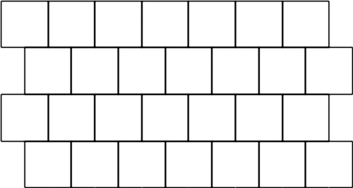 Offset square grid
The
Case for Hexes
My first experience of wargaming was board wargaming, where hexes are the norm, although some games use squares or areas. I’d not used hexes for miniatures until I played the first game on my new hex mat, and I was pleasantly surprised at how well they worked. Not needing to use a tape measure seemed to speed the game up much more than I’d expected, and I liked the complete certainty about what type of terrain a given unit was in. Each hex was wooded or not, for example, so if a unit was in a wooded hex, it was in a wood, and as soon as it moved out of that hex, it was no longer in the wood. There was no possibility for a unit to be only partially in a given type of terrain.
I’ve only used my hex mat for games with 3mm models, where each base represents a platoon. My hexes were sized so that each hex will accommodate a single base, and this seems to work well. I don’t think hexes will work very well for skirmish games with larger figures on single bases, however. In those types of games, I think I’d find the hexes too restrictive, and so I’ll stick with tape measures for those.
Hexes work for me, at least for higher-level games using small scale figures. If you want to give them a try, hopefully this article will mean that you’re able to create your own hex mat reasonably quickly and cheaply.
January 7, 2020
Soviet 73mm SPG-9 Kopye Recoilless Gun
Introduced in the late 1960s, the SPG-9 was a light anti-tank gun mounted on a tripod, with a four-man crew. When first seen by the West in 1969, it was given the provisional designation B-1968. By 1972 the correct designation was known.
Light enough to be carried by two soldiers, it could also be towed on a small two-wheeled carriage or mounted on a vehicle. A lighter version, the SPG-9D, could be carried by one man, and was used by air assault and airborne units. The PGO-9M optical sight was provided for direct fire, but PGO-K9 optical sights and PGN-9 night sights were also available. A device sometimes seen above the barrel was initially thought by NATO to be a spotting rifle, but was later confirmed to be a sub-calibre training device.
The SPG-9 fired fin-stabilised HEAT and HE-FRAG ammunition. The propellant charge was contained in an extension behind the folded fins, and fell away from the rest of the projectile after leaving the muzzle. A rocket motor inside the projectile ignited twenty metres from the muzzle, accelerating the projectile to full velocity. This combination produced a high muzzle velocity of 435m/s and a final velocity of 700m/s. The HEAT round could penetrate 400mm of armour, at a maximum range of 1,300m. The HE-FRAG round had an explosive charge of 753g of TNT, with a range of 4,500m.
Specifications: SPG-9
Calibre: 73mm
Weight of launcher: 47.5kg
Weight of tripod: 12kg
Length of launcher: 2.11m
Height of launcher: 399-900mm
Elevation: 25º
Maximum range: 1,300m (direct fire)
Maximum range: 4,500m (indirect fire)
Armour penetration: 400mm
Crew: 4


.jpg)